Method for determining the wear state

a technology of wear state and method, applied in the direction of machinability investigation, ways, instruments, etc., can solve the problems of insufficient wear material, insufficient wear material, and continuous wear process of tools used, in particular milling chisels

Active Publication Date: 2013-02-26
WIRTGEN GMBH
View PDF12 Cites 72 Cited by
  • Summary
  • Abstract
  • Description
  • Claims
  • Application Information

AI Technical Summary

Benefits of technology

[0014]According to this invention, the comparison of the position value to the reference value is used to establish a reference value that includes quantitative information about the wear on the milling tool, in particular on the chisel and / or chisel holder. It is then possible to evaluate the extent of wear, which assists the user with decision-making. It is thus possible for the user to decide whether a tool replacement must be carried out or whether the wear state permits continuation of a current milling task. This makes it possible to achieve a significant improvement in efficiency.
[0026]In one method embodiment of this invention, the wear on the chisel and the wear on the chisel holder are determined separately from each other in an additional calculation step. This makes it possible to obtain detailed system information that gives the user an exact picture of the wear on the system components.

Problems solved by technology

When stripping road surfaces by milling and when removing mineral deposits with surface miners likewise by milling, the tools used, in particular milling chisels, are subject to a continuous wear process.
Replacement of the chisel may be needed because there is no longer sufficient wear material, particularly hard metal at the tip.
The penetration resistance becomes too great, causing the efficiency to decrease, such as from excessive frictional loss.
Replacement of the chisel holder may be needed because the wear limit is reached and the holder begins to wear at the contact surface between the chisel and the holder.
Non-rotationally symmetrical wear may appear on the chisel tip and / or on the chisel head due to insufficient rotational motion of the chisel during the milling process.
This results in a poor milling pattern as well as the risk of tool breakage since the supporting action of the chisel head is lost.
The chisel holder can also be subject to additional non-rotationally symmetrical wear.
The chisel may also need replacement because of breakage.
Furthermore, worn and / or broken chisels can lead to secondary damage to the chisel holders and worn chisel holders can lead to secondary damage to the milling roller.
By contrast, it is not optimal from a cost standpoint for the chisels and / or chisel holders to be replaced too early because the chisels and chisel holders, as wearing parts, are very expensive.
This results in failure to properly utilize remaining wear potential.
Inspecting the wear state of the chisels and holders is very time-consuming and is also unproductive because no production can take place during this time.
Furthermore, due to the fact that the assessment is very prone to subjectivity, there is the risk of failure to optimally utilize the wear potential of the holders and chisels.
During operation of the milling machine, one problem arises if the milling process and the subsurface itself, whose properties fluctuate widely, have a large influence on the evaluation of the operating state of components.
Because of the widely fluctuating properties of the subsurface to be milled, it is not easy to differentiate between changing operating states of machine components directly or indirectly involved in the milling process that are attributable to changing surface properties and those that are attributable to changing tool properties.
This method is unable to provide a quantitative wear evaluation.

Method used


Image

  • Method for determining the wear state
  • Method for determining the wear state
  • Method for determining the wear state

Examples


Embodiment Construction

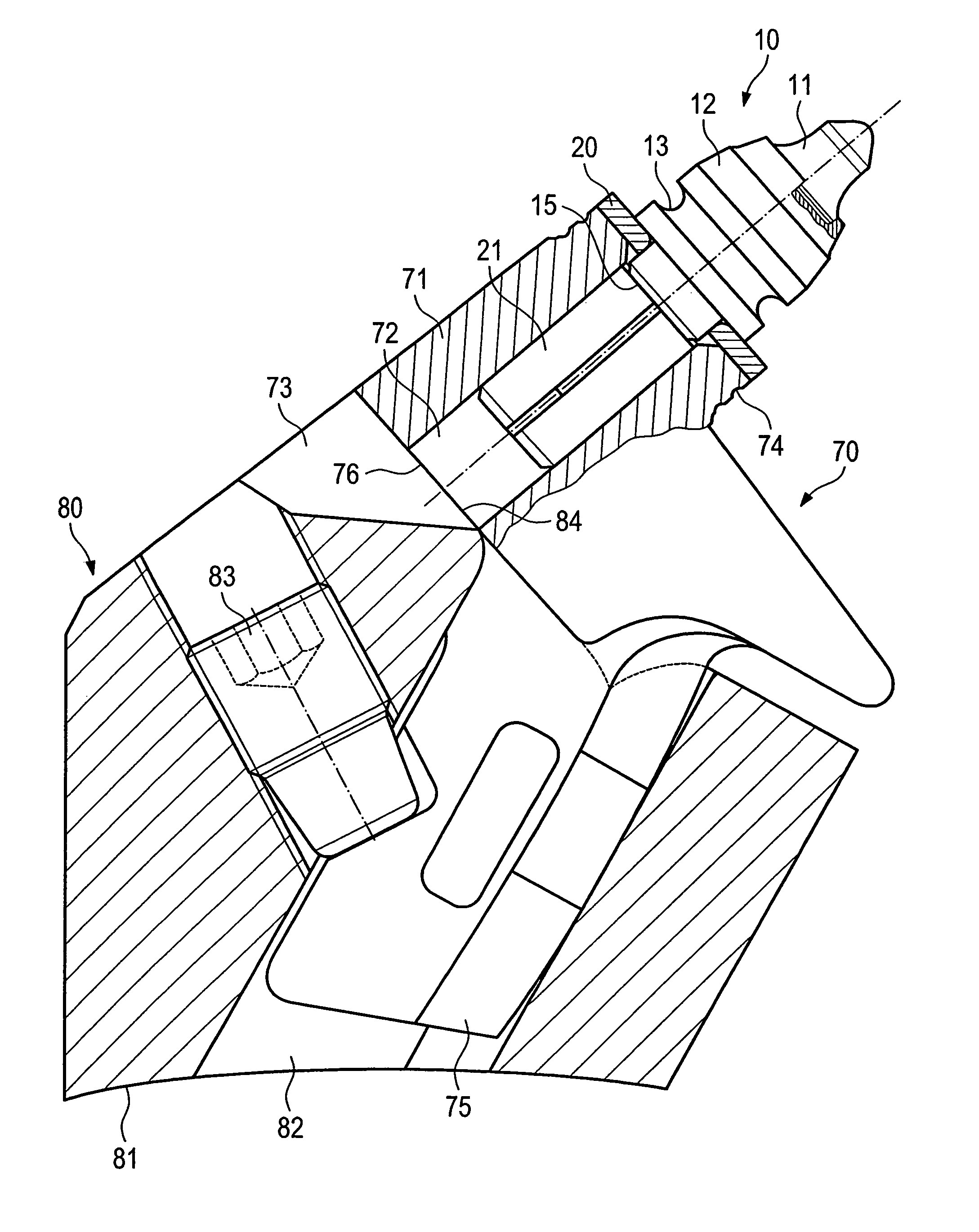
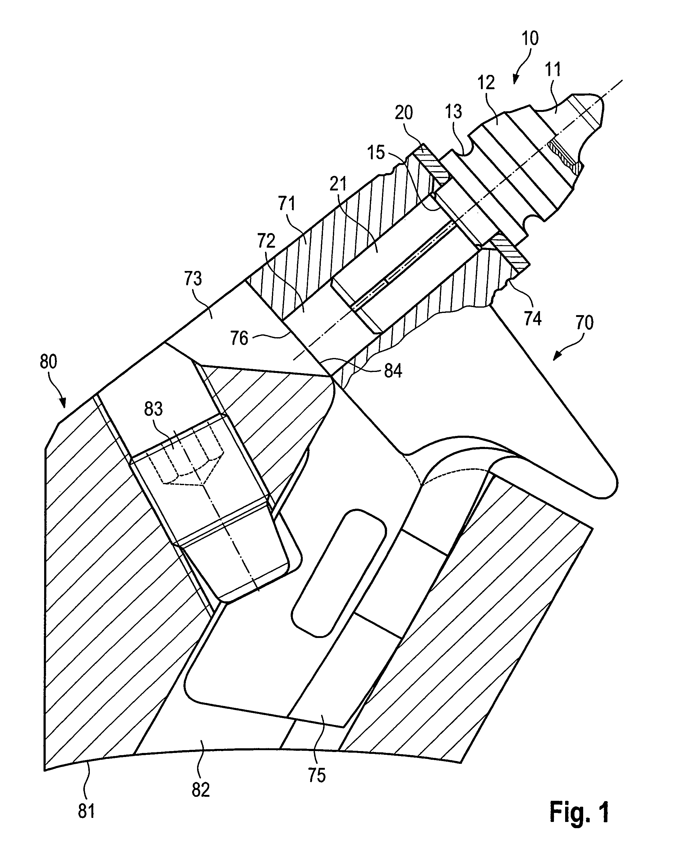
[0043]FIG. 1 shows an example of a chisel 10 of the type known from the prior art and described, for example, in German Patent Reference DE 38 18 213 A1. The chisel 10 has a chisel head 12 and a chisel shaft 15 integrally formed onto the chisel head 12. The chisel head 12 supports a chisel tip 11 composed of a hard material, for example hard metal.

[0044]The chisel tip 11 is usually soldered to the chisel head 12 along a contact surface. A circumferential extraction groove 13 is in the chisel head 12. This extraction groove 13 serves as a tool receptacle because a removing tool is placed onto it, enabling removal of the chisel 10 from a chisel holder 70.

[0045]The chisel shaft 15 supports a longitudinally slit, cylindrical clamping sleeve 21. This sleeve is secured so that it cannot be detached in the direction of the longitudinal span of the chisel 10, but is able to freely rotate in the circumferential direction on the chisel shaft 15. In the region between the clamping sleeve 21 an...


PUM


Abstract

This invention relates to a method for determining a wear state of a chisel, a chisel holder, and / or a chisel holder replacement system equipped with a chisel and chisel holder. For this method to give the user qualitative and quantitative information about the wear, according to one embodiment of this invention, a position of at least one point of the chisel and / or the chisel holder is determined by a contactless measurement method and a corresponding measurement result is compared in a switching unit to a reference value stored in a memory device.

Description

BACKGROUND OF THE INVENTION[0001]When stripping road surfaces by milling and when removing mineral deposits with surface miners likewise by milling, the tools used, in particular milling chisels, are subject to a continuous wear process. When the tools reach a certain wear state, it is advisable to replace them or the efficiency of the remainder of the process decreases. In this connection, it is necessary to differentiate among different wear states that lead to the replacement of a milling chisel or chisel holder.[0002]Replacement of the chisel may be needed because there is no longer sufficient wear material, particularly hard metal at the tip. The penetration resistance becomes too great, causing the efficiency to decrease, such as from excessive frictional loss. The wear is for the most part rotationally symmetrical.[0003]Replacement of the chisel holder may be needed because the wear limit is reached and the holder begins to wear at the contact surface between the chisel and t...

Claims


Application Information

Patent Timeline
Patent Type & Authority Patents(United States)
IPC IPC(8): G01B3/44E21B12/02E21C25/10E01C23/16
CPCB28D7/00G01N3/56G01N3/58E01C23/088E21C35/00G01B1/00E01C23/12G01B11/00
Inventor WAGNER, STEFANBARIMANI, CYRUSHAHN, GUNTER
Owner WIRTGEN GMBH
Why Eureka
Try Eureka