

Double trim tab
- Summary
- Abstract
- Description
- Claims
- Application Information
AI Technical Summary
Benefits of technology
Problems solved by technology
Method used
Image

Examples
Embodiment Construction
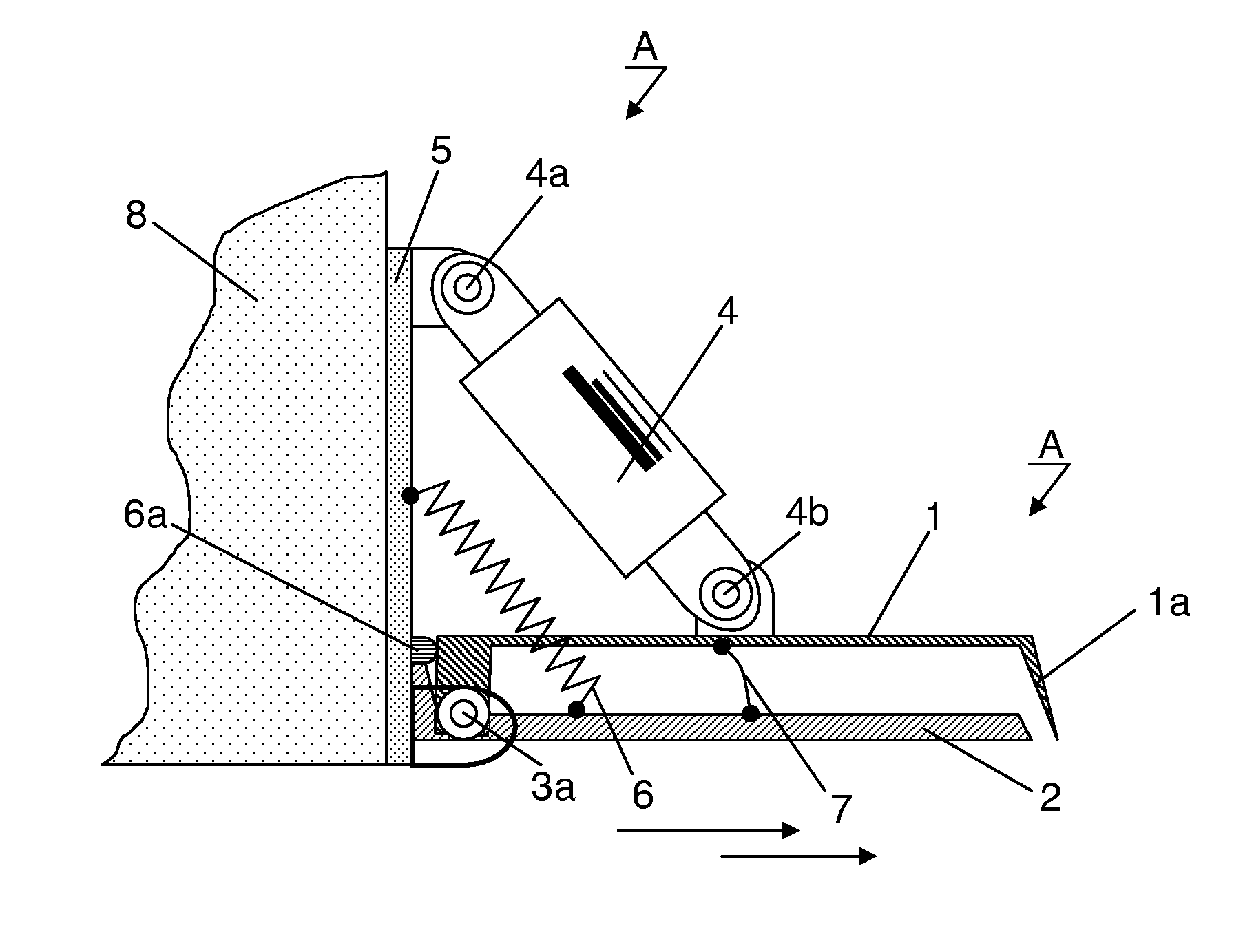
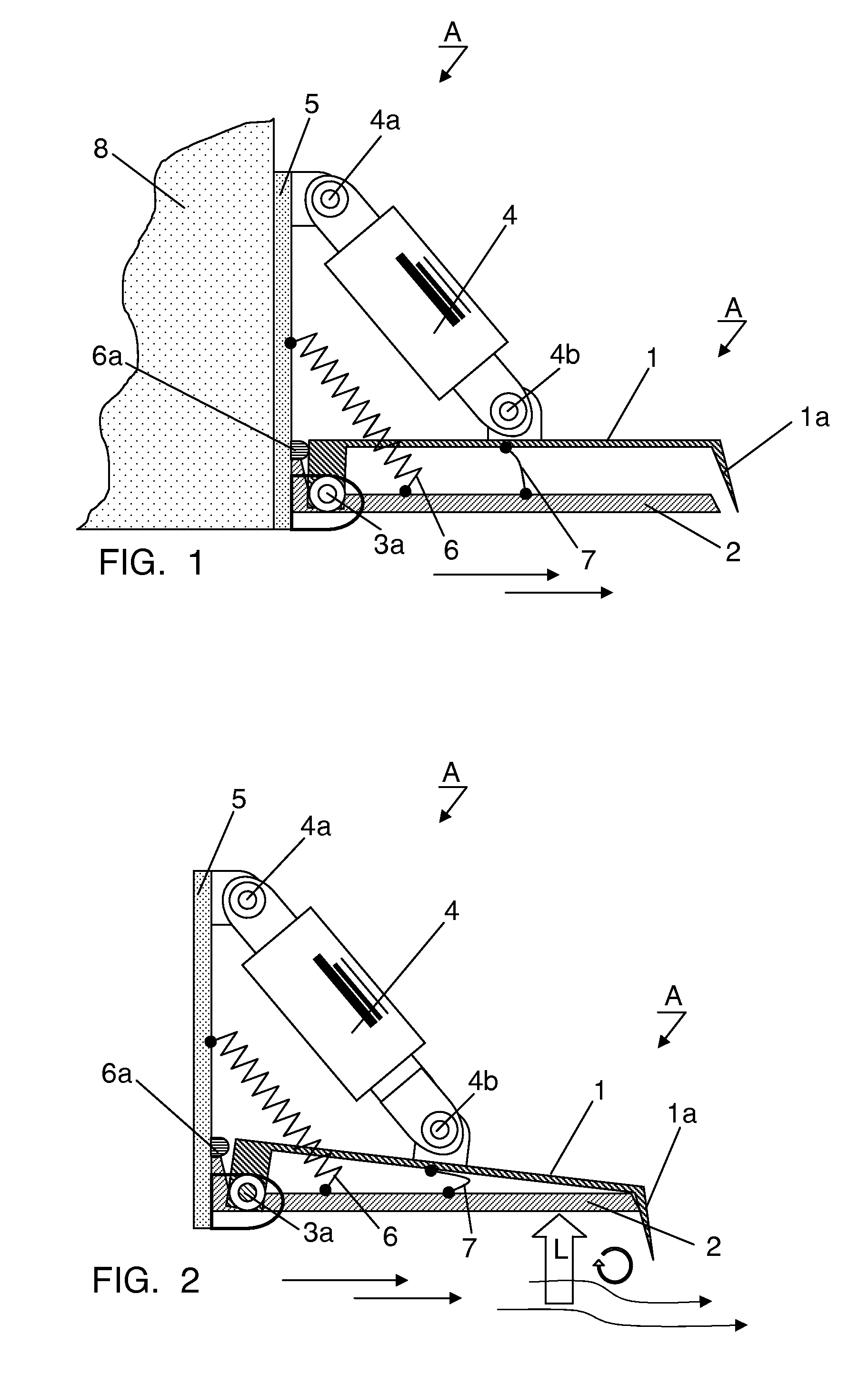
[0025]FIG. 1 shows a side elevation of double trim tab A in the starting position, consisting of flow interceptor 1 and bottom tab 2 and which are hinge-mounted via hinge 3a. Actuator cylinder 4 is attached to flow interceptor 1, hinge-mounted by bearing 4a, 4b, with actuation cylinder 4 being supported on transom 5.
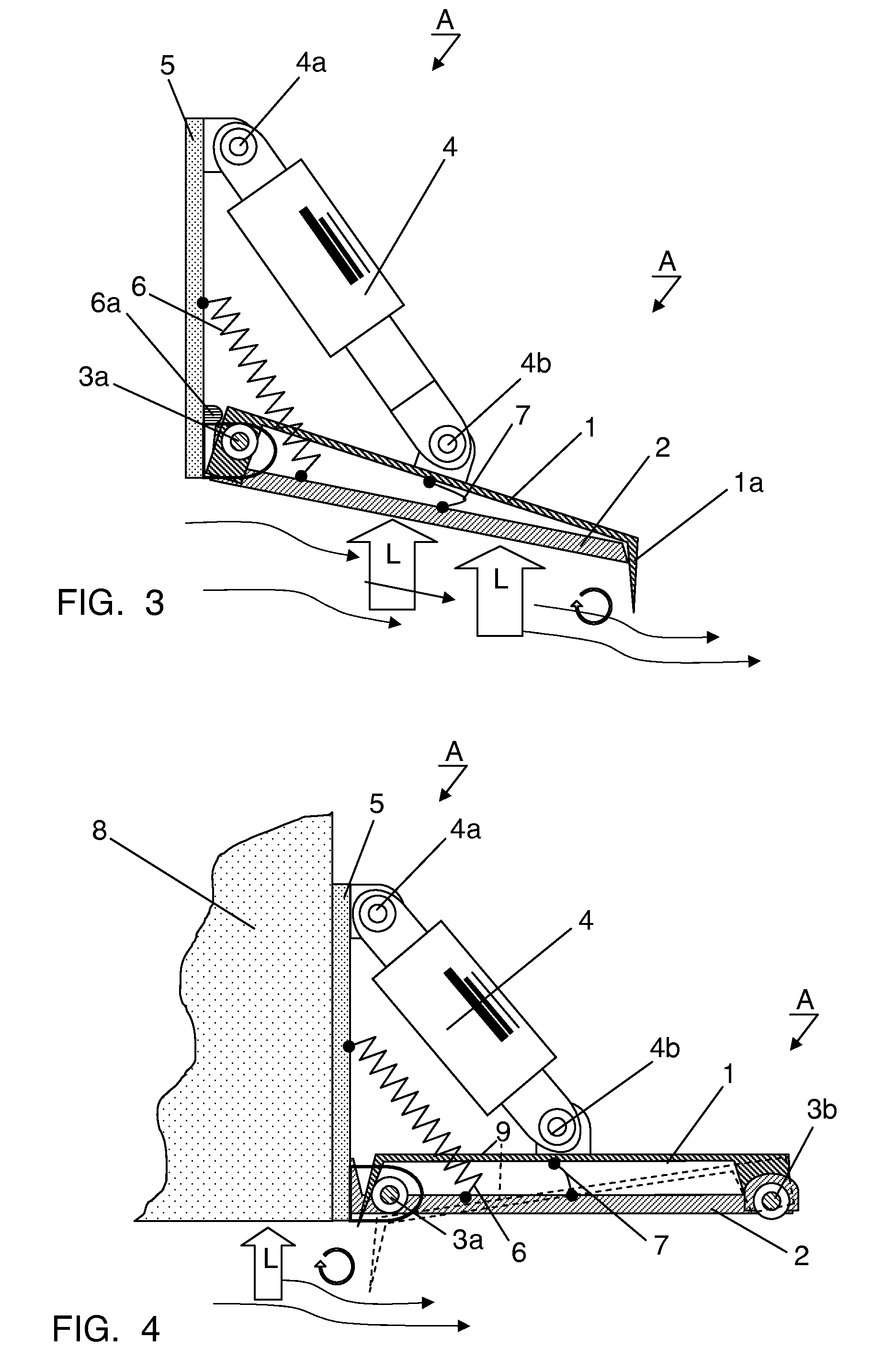
[0026]Return spring 6 is located on bottom tab 2 to guarantee that bottom tab 2 is located at limit stop 6a when not in use, thereby facilitating a defined alignment to water flow. In addition, bottom tab 2 is connected via flexible connecting device 7 with flow interceptor 1 so that even in the event of spring force losses bottom tab 2 can be completely raised by means of actuation cylinder 4 and the water flow, represented by arrows, can flow away unhindered behind the watercraft.
[0027]Actuation cylinder 4 can also be supported directly on stern 8 of a watercraft. Actuation cylinder 4 can be an electric drive or a fluid cylinder. If actuation cylinder 4 is a fluid cyli...
PUM
 Abstract
Description
Claims
Application Information