Corrugated metal ribbon heating element

Inactive Publication Date: 2005-11-08
CCI THERMAL TECH INC
View PDF2 Cites 46 Cited by
  • Summary
  • Abstract
  • Description
  • Claims
  • Application Information

AI Technical Summary

Benefits of technology

[0007]In accordance with the present invention, there, is provided a new and improved sheathed, electrical resistance heater having an internal corrugated ribbon heating element having a lower resistance value, e.g., 0.12 ohm/inch or less, than a round wire resistance element. Also, the percentage of the mass of the resistance heating element to

Problems solved by technology

When the coil wire is of fine gauge, it stretches easily during the extruding process, but as the wire diameter becomes large it becomes difficult to stretch the wire coils with conventional extruding pressures.
Also, as the diameter of the wire becomes larger, it is also more stiff and cannot be easily wrapped about a small diameter mandrel.
A significant shortcoming of this MI cable is that it does

Method used


Image

  • Corrugated metal ribbon heating element
  • Corrugated metal ribbon heating element
  • Corrugated metal ribbon heating element

Examples


Example

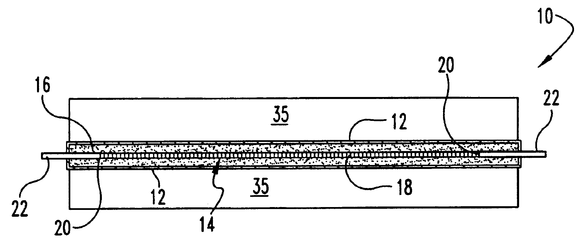
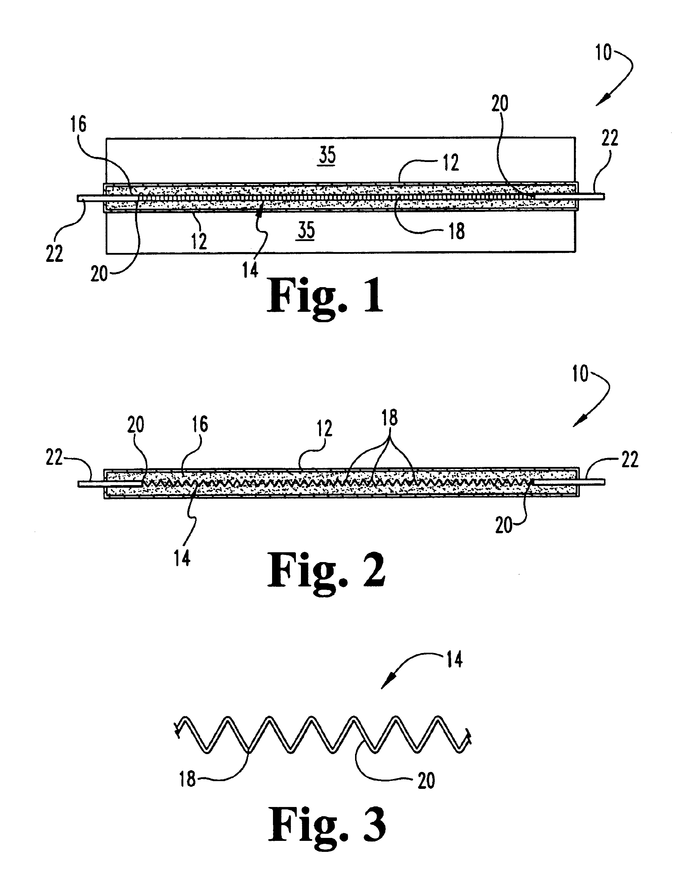
[0017]As shown in the drawings, the invention is embodied in a sheathed, electrical resistance heater 10 having an outer sheath tube or sheath 12 made of metal such as steel or aluminum. Within the sheath 12 is an internal electrical resistance heating element 14 made of a conventional metal such as an alloy having nickel, chrome or the like therein. Between the sheath 12 and the electrical resistance heating element 14 is an insulating material 16 such as a compacted magnesium oxide powder.

[0018]In some applications of the sheathed, electrical resistance heaters 10, the heater length desired may be quite long, e.g., 200 inches in length for the illustrated heater 10 shown in FIG. 5 with a very low resistance value of 0.05 ohm / inch when being operated at 120 or 240 volts. The cross-sectional area of the heater element may be quite small.

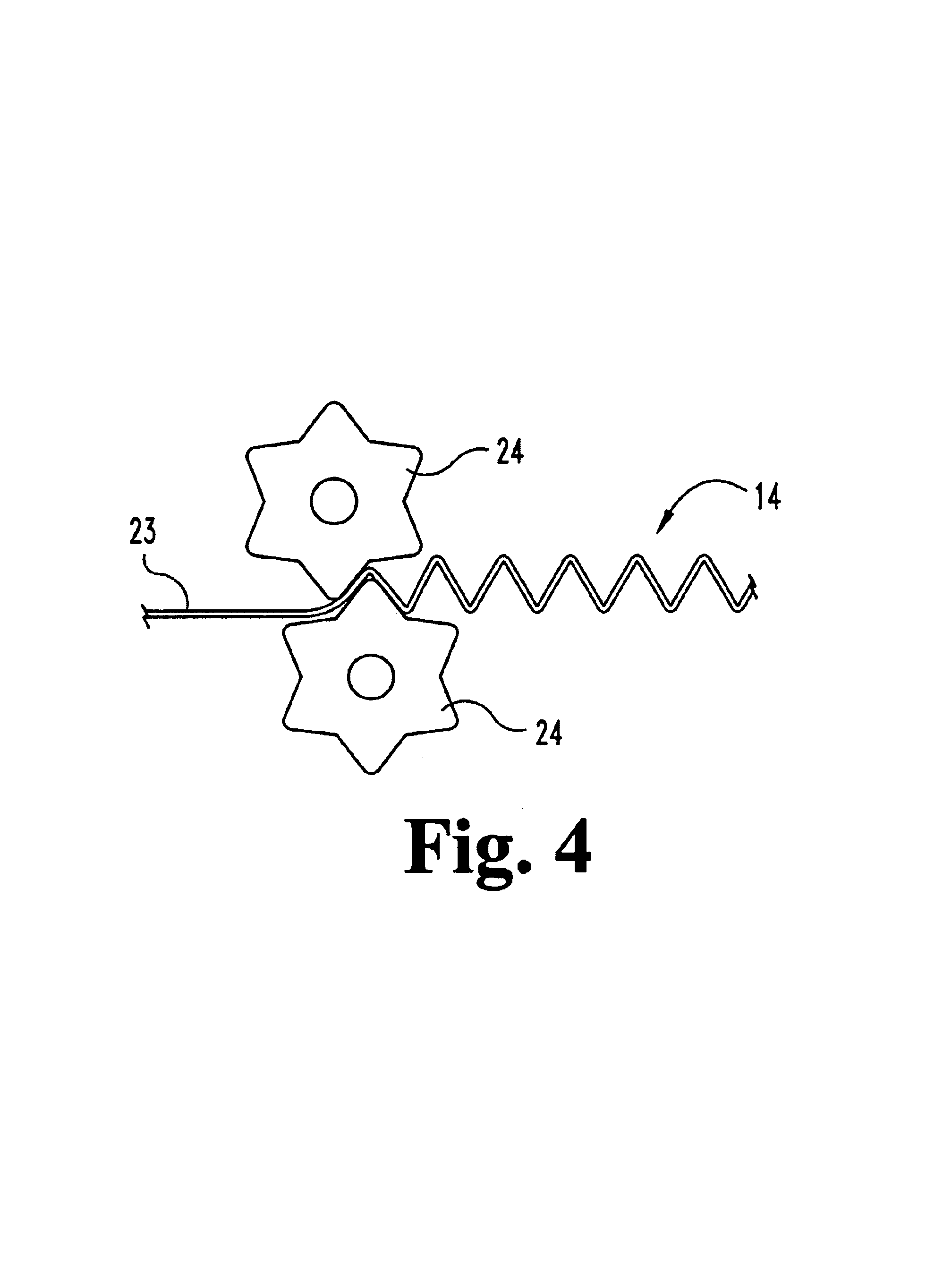
[0019]In accordance with the present invention, the sheathed electrical resistance beater 10 is provided with corrugations 18 in the electrical resi...


PUM


Abstract

A sheathed electrical resistance heater is provided with a metal corrugated resistance heating element located internally within a surrounding metal sheath and separated from the sheath by a compacted insulating material such as magnesium oxide. The preferred corrugated resistance element is a flat strip of metal that has been corrugated such as by passing the strip through the nip of a pair of gears. The corrugated strip resistance element is thicker than a foil and may be used to provide sheathed, electrical resistance heaters where it is too difficult to wind large diameter wires, which are desired for a low resistance ohm of 0.12 ohm/inch or less, on a small arbor to form a coiled wire resistance element. A heater may be formed with a resistance of 0.05 ohm/inch using the corrugated metal ribbon and may be 200 inches in length and have a finned sheath. Preferably, the sheath is compressed in a die to reduce the cross-sectional area of the heater without a substantial elongation of the sheath.

Description

[0001]This application is a provisional application of 60 / 302,772 filed Jul. 3, 2001FIELD OF THE INVENTION[0002]This invention relates to sheathed electrical resistance heaters having an outer metal sheath surrounding an internal resistance heating element and a compacted insulating material between the metal sheath and the internal resistance heating element, where the heater has a low resistance value.BACKGROUND OF THE INVENTION[0003]The conventional sheathed heating element uses a coiled wire as the resistance element that is able to elongate and contract as the electric element is turned on and turned off. The coiled wire is able to expand and contract in the manner of a coiled spring because of its coils without unduly stressing the resistance element itself or its connection with an electrical terminal which is usually a welded connection. The coiled resistance element accommodates different thermal—expansion coefficients of the different metals used for the sheath and for the...

Claims


Application Information

Patent Timeline
IPC IPC(8): H05B3/42H05B3/50
CPCH05B3/50
Inventor LUTZ, TIMOTHY P.
Owner CCI THERMAL TECH INC
Why Eureka
Try Eureka