Engine

a technology for engines and oil passages, applied in the field of engines, can solve the problems of easy oil leakage, risk of friction loss, and oil flowing through the oil passages, and achieve the effect of inhibiting or preventing the growth of unexpected friction loss

Inactive Publication Date: 2013-03-05
TOYOTA JIDOSHA KK
View PDF13 Cites 15 Cited by
  • Summary
  • Abstract
  • Description
  • Claims
  • Application Information

AI Technical Summary

Benefits of technology

[0013]This invention provides an engine in which a camshaft is rotatably supported by a cam housing mounted on a cylinder head, wherein oil that leaks from a supporting part provided at a forefront end of the camshaft is caused not to contact with a timing chain so that unexpected grow of friction loss can be inhibited or prevented.
[0015]According to this constitution, even if the oil leaks from the concave bearing that supports the camshaft provided at a forefront end of the cam housing, this leaking oil can be guided from the oil recovery part to the inner side of the peripheral wall of the cylinder head. Therefore, the phenomenon in which excessive amount of oil is supplied to the timing chain as in the related art can be avoided. Consequently, unexpected grow of friction loss that occurs in the related art can be inhibited or prevented.
[0021]According to this constitution, a front opening of the groove is enlarged by the presence of the slope, whereby the leaking oil can be received easily and recovery operation is improved.
[0026]However, even when such oil leakage occurs, the above constitution enables guiding of the leaking oil to the inner side of the peripheral wall of the cylinder head through the oil recovery part. Consequently, the phenomenon in which excessive amount of oil is supplied to the timing chain as in the related art can be avoided. As a result, unexpected grow of friction loss that occurs in the related art can be inhibited or prevented.
[0029]According to this invention, even when the oil leaks from the supporting part provided at the forefront end of the camshaft, this oil can be caused not to contact with the timing chain. Therefore, unexpected grow of friction loss that occurs in the related art can be inhibited or prevented.

Problems solved by technology

As in the related art described above, in a case where part of the oil passages for supplying and recovering the oil to and from the controller and oil control valve of the variable valve timing mechanism is provided in the cam cap and camshaft attached to the forefront-end concave bearing of the cam housing, there is a possibility that the oil flowing through the oil passages leaks from a sliding contact surface where the forefront-end concave bearing of the cam housing and the cam cap come into sliding contact with the journal part positioned at the forefront end of the camshaft, into a timing chain cover.
For this reason, the oil leakage occurs easily.
Therefore, when the oil that leaks into the timing chain cover contacts with the timing chain, there is a risk of friction loss that is caused by rotation resistance of a timing chain.
Especially when the oil leaking from the sliding contact surface into the timing chain in spite of the system that lubricates the timing chain using the oil, excessive amount of oil is supplied to the timing chain, resulting in unexpected grow of friction loss.
Note that even in an engine that is not mounted with the above variable valve timing mechanism, oil leaks from a sliding contact surface where a forefront-end journal part of the camshaft comes into sliding contact with the concave bearing of the cam housing and with the cam cap.

Method used


Image

  • Engine
  • Engine
  • Engine

Examples


first embodiment

[0043]The best embodiments of the invention are described hereinafter in detail with reference to FIGS. 1 to 12. First, the invention is shown in FIGS. 1 to 9.

[0044]An overview of an engine used on the first embodiment is described with reference to FIGS. 4 to 6.

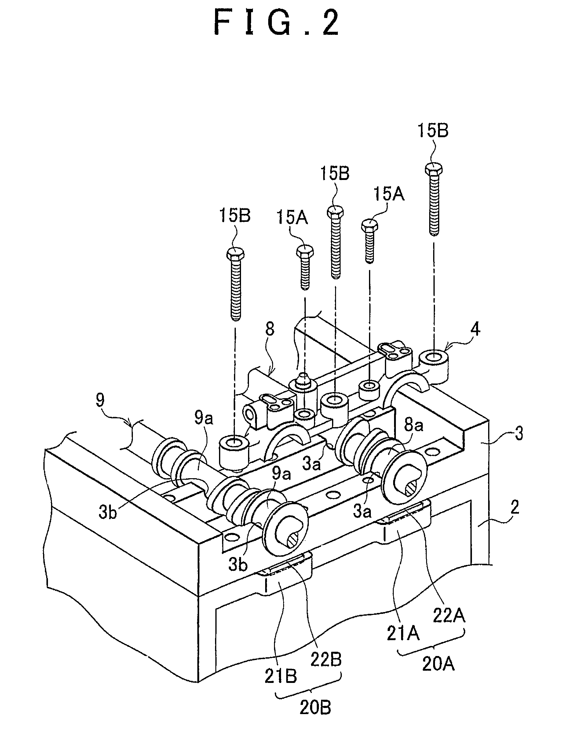
[0045]FIG. 4 is an exploded perspective view showing a part of the engine common to the embodiments of the invention. FIG. 5 is a side view showing a fractured front end side of the engine of FIG. 4. FIG. 6 is a front view showing a state in which a timing chain cover is removed from the engine shown in FIG. 5.

[0046]In the engine of this specification, the side in which a timing chain (or a timing belt) is disposed represents the front of the engine in order to clarify the meanings of “front end” and “rear end.”

[0047]Note that the basic configuration or principle of operation of the engine is a conventional matter, the parts related to the characteristics of the first embodiment are described in detail, and thus the detailed...

second embodiment

[0095](3) this invention is described in detail with reference to FIGS. 10 to 12.

[0096]The second embodiment also has oil recovery parts 20A, 20B that basically play the same roles as the oil recovery parts 20A, 20B of the first embodiment, but the structures of the oil recovery parts 20A, 20B of the second embodiment are different from those of the first embodiment.

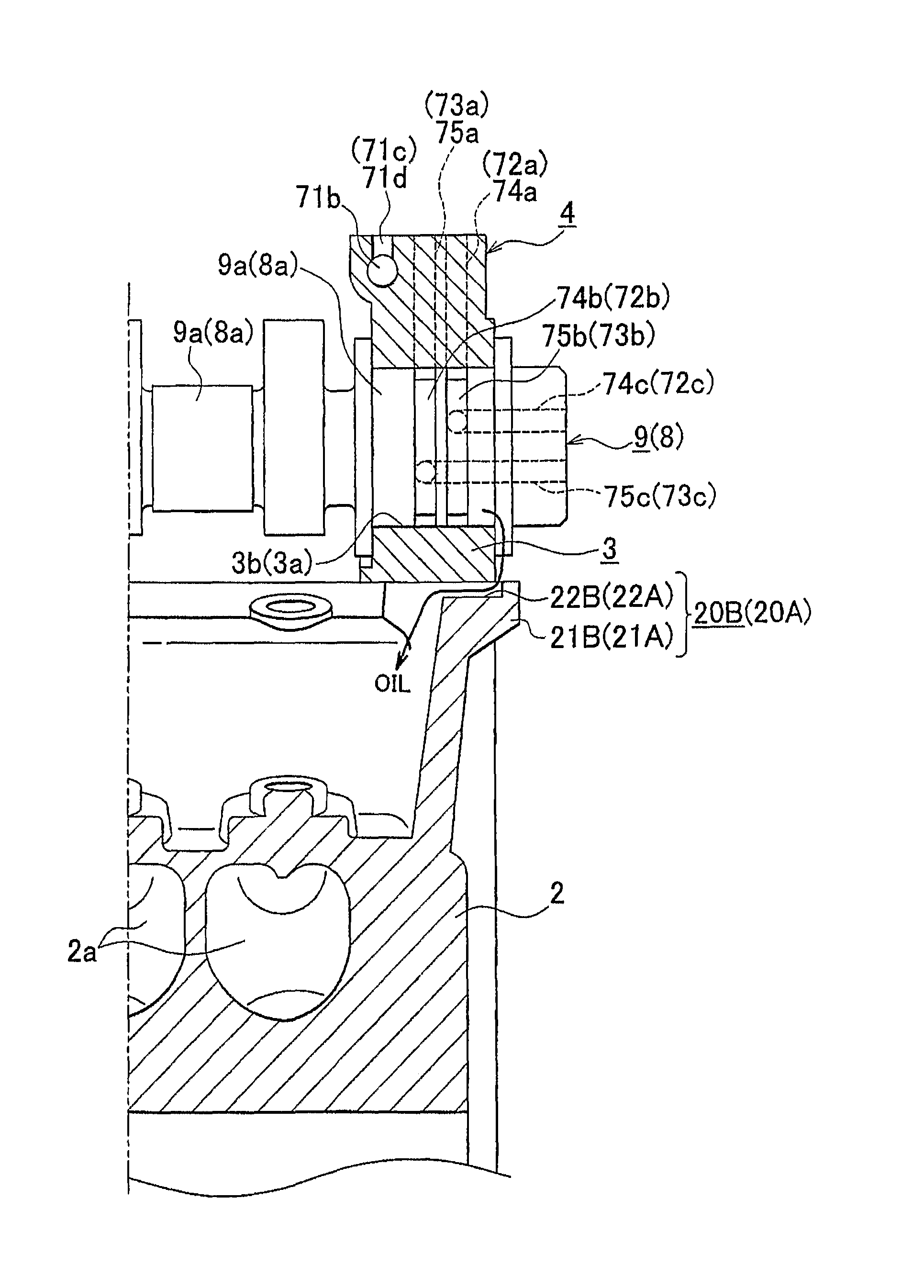
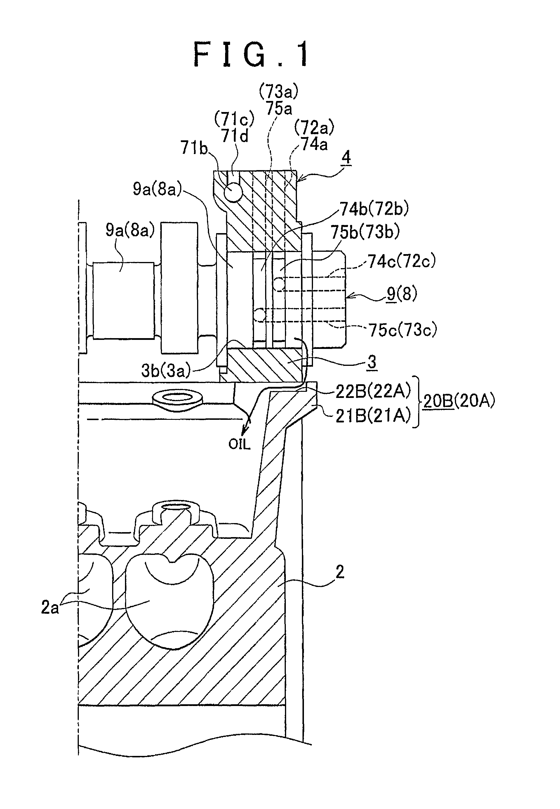
[0097]Each of the oil recovery parts 20A, 20B is configured by a projecting parts 21A, 21B provided at a front wall upper end of a cylinder head 2, a groove 22A, 22B provided in the projecting part 21A, 21B, and a tapered slope 23A, 23B provided at a front end lower corner of a concave bearing 3a, 3b provided at a forefront end of a cam housing 3.

[0098]Each of the grooves 22A, 22B is provided over the area between a leading end of each of the projecting parts 21A, 21B and a front wall of the cylinder head 2, that is, along the entire length of the front wall of the cylinder head 2 in its front-back direction.

[0099]Howeve...


PUM


Abstract

An oil recovery part (20A, 20B) for guiding oil to an inner side of a peripheral wall of a cylinder head (2) is provided at a front wall upper end of the cylinder head (2), the oil leaking from a concave bearing (3a, 3b) that supports a camshaft (8, 9) provided at a forefront end of a cam housing (3).

Description

FIELD OF THE INVENTION[0001]This invention relates to an engine (also called internal combustion engine) in which a camshaft is supported rotatably by a cam housing attached onto a cylinder head, and more particularly to an improved structure for oil to flow from a supporting part of a journal part positioned at a forefront end of the camshaft.BACKGROUND OF THE INVENTION[0002]Japanese Patent Application Publication No. 5-86913 (JP-A-5-86913) discloses an engine mounted with a hydraulically-driven variable valve timing mechanism for changing valve timing.[0003]This variable valve timing mechanism is a mechanism capable of changing the timing of opening and closing at least one of intake and exhaust valves by advancing or retarding a rotational phase of at least one of intake and exhaust camshafts in relation to a rotational phase of a crankshaft.[0004]The abovementioned hydraulically-driven variable valve timing mechanism has a controller that is constituted by a vane actuator instal...

Claims


Application Information

Patent Timeline
Patent Type & Authority Patents(United States)
IPC IPC(8): F01L1/34
CPCF01L1/022F01L1/053F01L1/3442F01M9/102F01M11/02F01L1/02F01L2001/0476F01L2001/0537F01L2001/34433F01L2001/34496F01L2810/02F01M2011/023
Inventor IWATA, YASUSHI
Owner TOYOTA JIDOSHA KK
Why Eureka
Try Eureka