Symbol mapping method for repetition channel coding

a repetition channel and mapping method technology, applied in the field of symbol mapping methods, can solve the problems of poor decoding throughput, deterioration of specific code bits, etc., and achieve the effects of low reliability, maximum reliability, and high accuracy

Active Publication Date: 2013-03-05
OPTIS CELLULAR TECH LLC
View PDF20 Cites 10 Cited by
  • Summary
  • Abstract
  • Description
  • Claims
  • Application Information

AI Technical Summary

Benefits of technology

[0015]An object of the present invention is to provide a symbol mapping method for repetition channel coding which enables maximum reliability in a receiving side by mapping codeword bits with subcarriers to reduce the number of bits having low reliability when a transmitting side uses repetition coding.
[0017]In another aspect of the present invention, a symbol mapping method according to another embodiment of the present invention comprises performing repetition coding on codeword to output repeated codeword symbols, and mapping the repeated codeword symbols with subcarriers located at a distributed resource block in a manner that a distance between the subcarriers can be maximized.
[0018]According to the embodiments of the present invention, it is possible to obtain maximum reliability in a receiving side by mapping codeword bits with subcarriers to reduce the number of bits having low reliability when a transmitting side uses repetition coding. Also, it is possible to improve decoding throughput and obtain channel diversity.

Problems solved by technology

However, in an actual communication system, a code rate lower than that of the designed channel coding may be required considering system coverage and throughput deterioration in a specific position within a cell.
Namely, reliability of specific code bits may be deteriorated by deep fading of channel.
Particularly, if codewords become a multiple of a specific length, effect according to repetition is simply changed to chase combining, and very poor decoding throughput is caused.

Method used


Image

  • Symbol mapping method for repetition channel coding
  • Symbol mapping method for repetition channel coding
  • Symbol mapping method for repetition channel coding

Examples


Embodiment Construction

[0029]Hereinafter, the preferred embodiments of the present invention will be described with reference to the accompanying drawings. However, it is to be understood that various modifications can be made in the following embodiments of the present invention, and the scope of the present invention is not limited to the following embodiments.

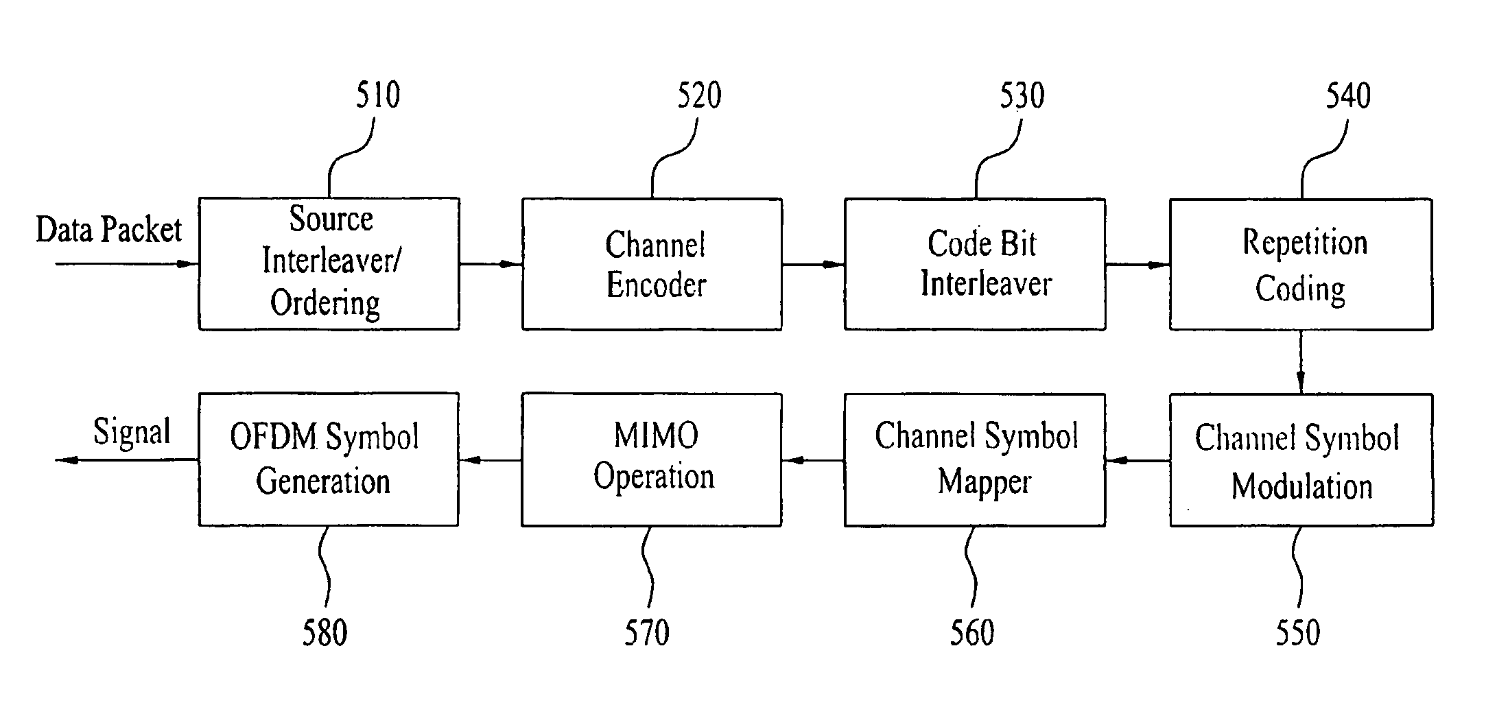
[0030]The embodiments of the present invention can be divided in accordance with a position at which a repetition can be performed. Examples of the position at which the repetition can be performed include a case where repetition is applied in a bit level and a case where repetition is applied in a symbol level. Also, examples of the position to which repetition can be applied include a case where repetition is applied before performing interleaving by an interleaver and a case where repetition is applied after the interleaving.

[0031]However, repetition of source bits or repetition before the interleaving is not proper. Instead, if repetition is p...


PUM


Abstract

A symbol mapping method for repetition coding is disclosed. The symbol mapping method comprises performing repetition coding on codeword to output repeated codeword symbols, and mapping the repeated codeword symbols with subcarriers located in different localized resource blocks. According to the embodiments of the present invention, it is possible to obtain maximum reliability in a receiving side by mapping codeword bits with subcarriers to reduce the number of bits having low reliability when a transmitting side uses repetition coding. Also, it is possible to improve decoding throughput and obtain channel diversity.

Description

CROSS-REFERENCE TO RELATED APPLICATIONS[0001]Pursuant to 35 U.S.C. §119(a), this application claims the benefit of earlier filing date and right of priority to Korean Patent Application No. 10-2008-22477, filed on Mar. 11, 2008, and pursuant to 35 U.S.C. §119(e), this application also claims the benefit of U.S. Provisional Application No. 61 / 018,674, filed on Jan. 3, 2008, the contents of which are all hereby incorporated by reference herein in their entirety.BACKGROUND OF THE INVENTION[0002]1. Field of the Invention[0003]The present invention relates to a symbol mapping method, and more particularly, to a method for mapping codeword bits with subcarriers to reduce the number of bits having low reliability when a receiving side uses repetition coding.[0004]2. Discussion of the Related Art[0005]For wireless communication, channel coding is designed to minimize its option considering complexity of a receiving side and a transmitting side. However, in an actual communication system, a ...

Claims


Application Information

Patent Timeline
Patent Type & Authority Patents(United States)
IPC IPC(8): H04K1/02H04L25/03
CPCH04L1/08H04L5/0007H04W72/0406H04L5/0042H04L5/0044H04L5/0058H04L1/0071H04L5/0023H04L1/18H04L27/26H04W72/20
Inventor KWON, YEONG HYEONHAN, SEUNG HEELEE, HYUN WOOMOON, SUNG HOKWAK, JIN SAMKIM, DONG CHEOLNOH, MIN SEOK
Owner OPTIS CELLULAR TECH LLC
Why Eureka
Try Eureka