Automated vehicle fueling apparatus and method

a fueling apparatus and automatic technology, applied in the direction of liquid handling, instruments, packaged goods types, etc., can solve the problems of difficult control of vehicle positioning, vehicle positioning errors, and vehicle positioning relative to fuel receiving apertures

Inactive Publication Date: 2013-03-12
HOLLERBACK JAMES A
View PDF8 Cites 36 Cited by
  • Summary
  • Abstract
  • Description
  • Claims
  • Application Information

AI Technical Summary

Benefits of technology

[0015]Stronger formulas of gasoline can be blended without fear of damage to human eyes, ears, nose, throat, skin or lungs.
[0016]Diesel fuel spills and TAH are

Problems solved by technology

The apparatus was not able to defuel the vehicle tank.
Errors in positioning of the vehicle and positioning

Method used


Image

  • Automated vehicle fueling apparatus and method
  • Automated vehicle fueling apparatus and method
  • Automated vehicle fueling apparatus and method

Examples


Embodiment Construction

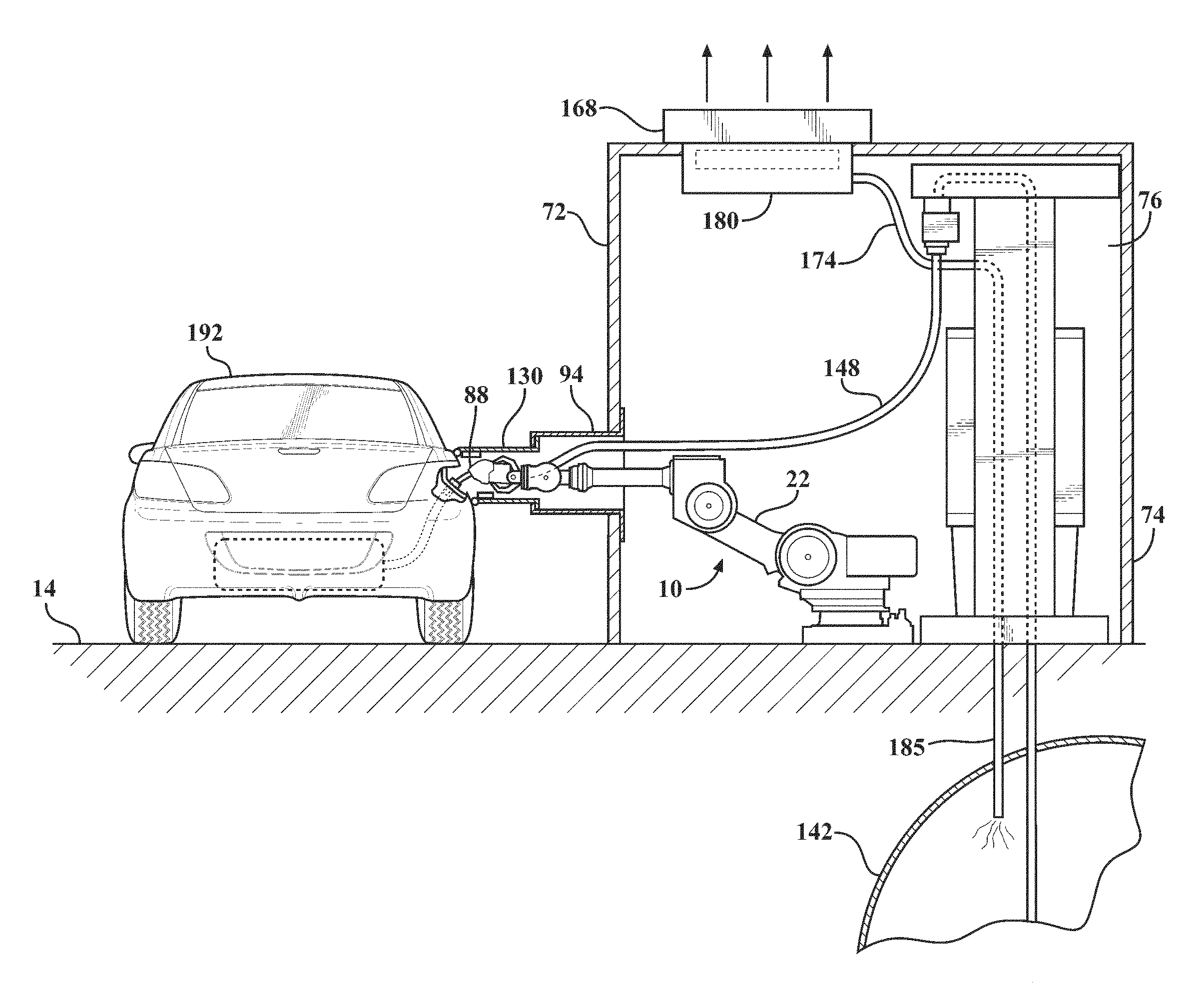
[0028]The robot 10, as shown in FIG. 1, includes a fixed robot base 12. The base 12 is clamped to a concrete slab 14 by bolts embedded in the slab and passing through bores 16 through the base. A pivotable base 18 is journaled on the fixed robot base 12 for pivotal movement about a base axis 20. A first arm 22 is pivotally attached to the pivotable base 18. The first arm 22 pivots about a first arm axis 24 which is perpendicular to the base axis 20. A second arm assembly 26 is pivotably attached to the first arm 22 for pivotal movement about a second arm axis 28. The second arm axis 28 is parallel to the first arm axis 24.

[0029]The second arm assembly 26 includes a second arm elbow housing 30 that is journaled on the first arm 22. An elongated second arm portion 32 is pivotally attached to the elbow housing 30. The elongated second arm portion 32 pivots about an elongated second arm portion axis 34. The elongated second arm axis 34 is transverse to and offset from the second arm axi...


PUM

PropertyMeasurementUnit
Distanceaaaaaaaaaa

Abstract

A multi axis robot is mounted in a fuel transfer housing. A programmable controller is connected to the robot. A control console receives instructions, from a vehicle operator who remains in an operator's station, and transmits instructions to the controller. Cameras locate the vehicle fueling port. A tube is extended from the transfer housing toward the fueling port. The port is opened by robot arm and tools extending through the tube. The cap is stored. A fuel discharge is connected to the port. A fuel pump is activated and then deactivated. The fuel discharge is removed from the port. The robot retrieves the fuel cap, closes the port and closes other port covers. The tube is retracted into the transfer housing. During fueling air and fuel vapors are sucked into the housing. Filters separate air. Captured fuel is returned to storage. The operator and vehicle separate from the fuel housing.

Description

CROSS REFERENCE TO RELATED APPLICATION[0001]This application claims the benefit of the filing date of U.S. Provisional Application No. 61 / 299,934 titled AUTOMATIC GROUND REFUELING USING A TELESCOPING PLENUM filed Jan. 30, 2010.TECHNICAL FIELD[0002]The invention is in an apparatus for fueling and defueling vehicles, capturing fuel vapors from the vehicle and fuel storage tank, and a method of operating the apparatus.BACKGROUND OF THE INVENTION[0003]Apparatus has been used for automated fueling of land vehicles. All of these land vehicles were modified to have a special fueling port in one specific location on the vehicle. One wheel of the vehicle was locked in a predetermined location during fueling. Fuel spilled during vehicle filling was received in a sump. Vapors from the vehicle tank were not captured. Vapors from the fuel in the sump were not captured. The apparatus was not able to defuel the vehicle tank. Errors in positioning of the vehicle and positioning of the fuel supply t...

Claims


Application Information

Patent Timeline
IPC IPC(8): B65B31/00
CPCB67D7/0401B25J21/00B25J19/0075B25J11/00
Inventor HOLLERBACK, JAMES A.
Owner HOLLERBACK JAMES A
Why Eureka
Try Eureka