
Method and system for eliminating fuel consumption during dynamic braking of electric drive machines

a technology of electric drive machine and dynamic braking, which is applied in the direction of motor/generator/converter stopper, electric device, dynamo-electric converter control, etc., can solve the problems of increasing fuel consumption during propel mode, increasing weight of vehicle, and introducing significant cost and technological limitations, so as to eliminate fuel consumption during dynamic braking

Inactive Publication Date: 2013-03-12
CATERPILLAR INC
View PDF19 Cites 29 Cited by
  • Summary
  • Abstract
  • Description
  • Claims
  • Application Information

AI Technical Summary

Benefits of technology

The present patent is about a drive system for a machine that reduces fuel consumption during dynamic braking. The system includes an inverter circuit and an auxiliary driver that automatically communicate power from the engine and any auxiliary devices to the motor in a propel mode and from the motor to the engine in a dynamic braking mode. This results in a minimal amount of fuel being consumed during dynamic braking. The method also includes determining the current mode of operation of the machine and directing electrical power from the generator to the motor in a propel mode and from the motor to the engine in a dynamic braking mode. This technology helps to optimize energy usage and reduce emissions in electric drive machines.

Problems solved by technology

While such strategies for absorbing the machine's kinetic energy may prove useful, there are some significant drawbacks.
Although such storage configurations may reduce fuel consumption during retarding modes, the extra weight added to the vehicle may in fact increase fuel consumption during propel modes.
Implementing storage configurations also introduces significant cost and technological limitations, among other things.
However, retarding grid configurations introduce several control limitations.
Among other things, these configurations prohibit operation of the grid cooling system without providing significant braking force.
More specifically, because the grid cooling system is powered only by waste energy that is supplied by the motor during retarding modes, the grid cooling system is unable to operate once the machine exits the retarding mode without absorbing a prohibitively large amount of power from the engine and consuming diesel fuel.
Furthermore, in low-power retarding modes, or when the retarding arrangement is operating at less than nominal power, the shared DC bus of the drive system may collapse due to the comparatively large retarding requirement.
However, the retarding grids and the grid cooling mechanisms of such systems are linked to the same bus, and thus, cannot be independently controlled.

Method used


Image

  • Method and system for eliminating fuel consumption during dynamic braking of electric drive machines
  • Method and system for eliminating fuel consumption during dynamic braking of electric drive machines
  • Method and system for eliminating fuel consumption during dynamic braking of electric drive machines

Examples


Embodiment Construction

[0020]Reference will now be made in detail to specific embodiments or features, examples of which are illustrated in the accompanying drawings. Generally, corresponding reference numbers will be used throughout the drawings to refer to the same or corresponding parts.

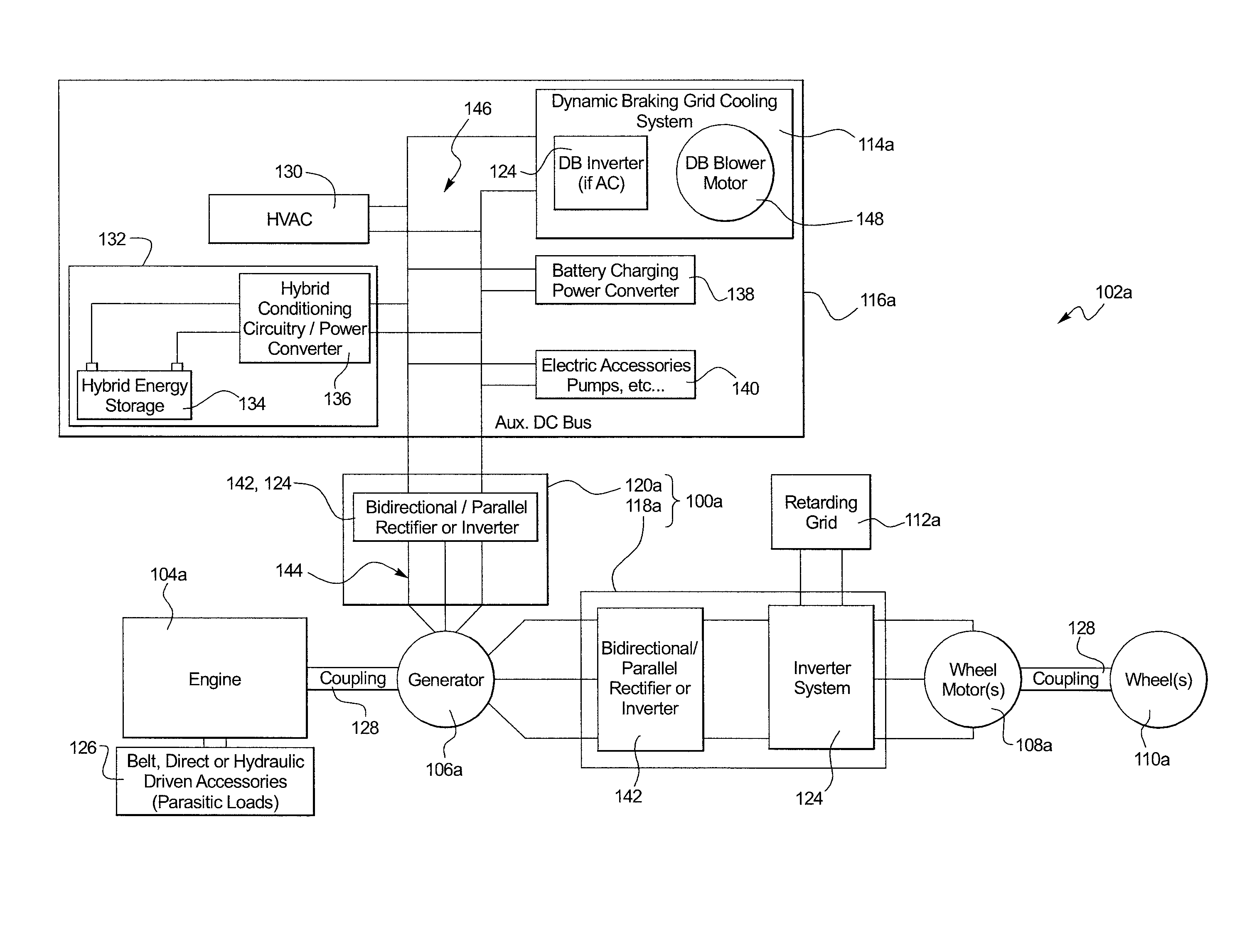
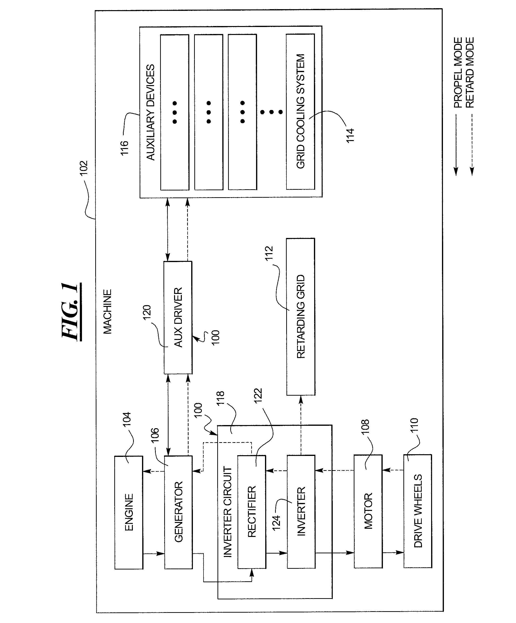
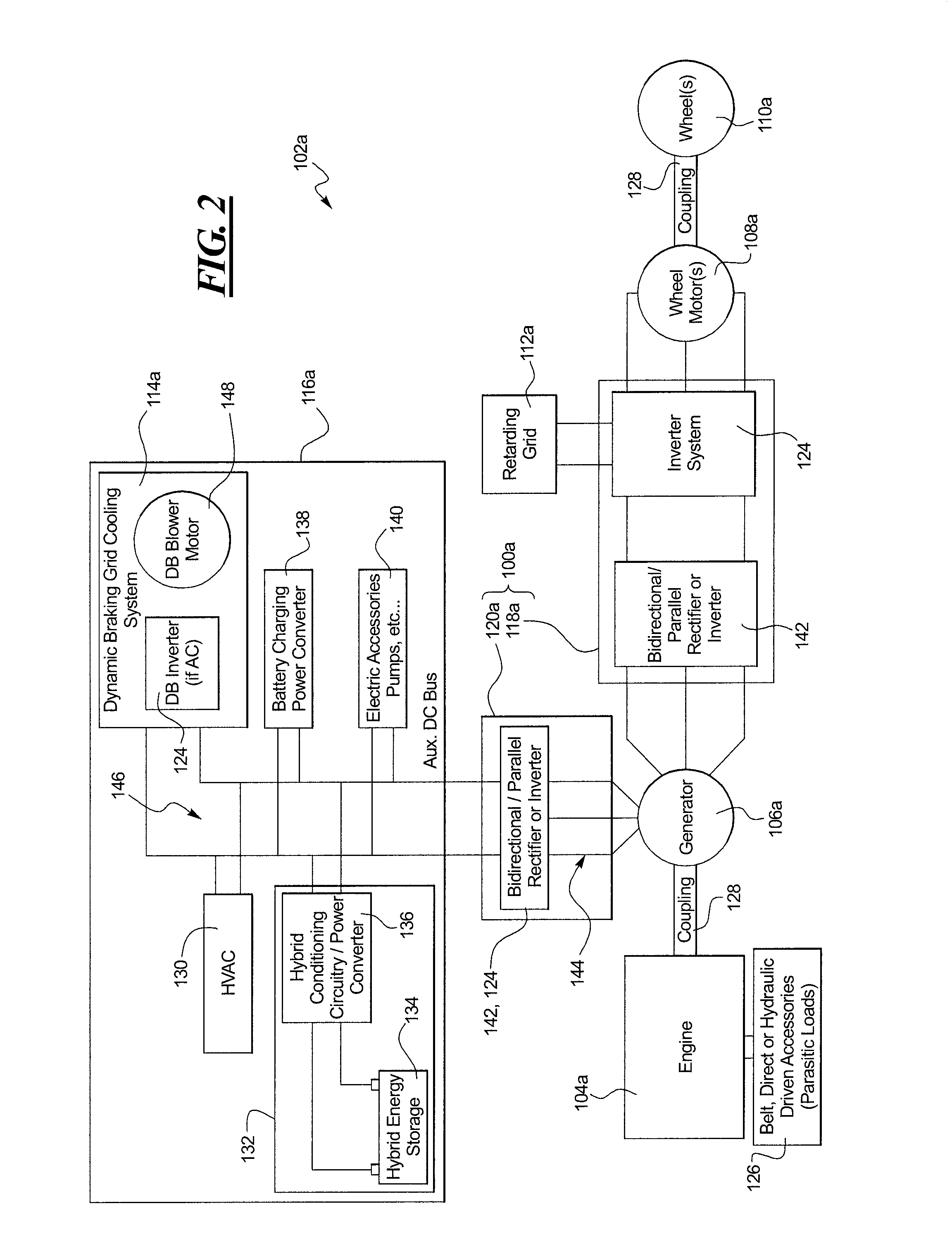
[0021]FIG. 1 schematically illustrates an exemplary drive system 100 as applied to an electric drive machine 102, such as an off-road truck, or the like. The electric drive machine 102 may include an engine 104, a generator 106, one or more traction motors 108, one or more final drive wheels 110, a retarding grid 112, a grid cooling system 114 and one or more auxiliary devices 116. As shown, the drive system 100 may provide the machine 102 with at least an inverter circuit 118 and an auxiliary driver 120. The inverter circuit 118 may include one or more rectifiers 122, inverters 124, or any combination thereof, and be disposed between the generator 106 and the motor 108. The auxiliary driver 120 may be disposed between ...


PUM


Abstract

A drive system for an electric drive machine having an engine, a generator, a motor, final drive wheels and auxiliary devices is provided. The drive system may include an inverter circuit and an auxiliary driver. The inverter circuit may be coupled to each of the generator and the motor. The auxiliary driver may be coupled to each of the generator and the auxiliary devices. The inverter circuit and the auxiliary driver may be configured to automatically communicate power from the engine and any power from the auxiliary devices to the motor in a propel mode, and automatically communicate power from the motor to the engine, and optionally to a hybrid system if applicable, in a dynamic braking mode so as to minimize fuel consumption during the dynamic braking mode.

Description

TECHNICAL FIELD[0001]The present disclosure relates generally to the operation of electric drive machines, and more particularly, to systems and methods that eliminate fuel consumption during dynamic braking.BACKGROUND[0002]Electric drive systems for machines typically include a power circuit that selectively activates a motor at a desired torque. The motor is typically connected to a wheel or other traction device that operates to propel the machine. An electric drive system includes a prime mover, for example, an internal combustion engine, that drives a generator. The generator produces electrical power that is used to drive the motor. When the machine is propelled, mechanical power produced by the engine is converted to electrical power at the generator. This electrical power is often processed and / or conditioned before being supplied to the motor. The motor transforms the electrical power back into mechanical power to drive the wheels and propel the vehicle.[0003]The machine is...

Claims


Application Information

Patent Timeline
Patent Type & Authority Patents(United States)
IPC IPC(8): H02P3/12
CPCB60L1/003B60L7/14Y02T90/16
Inventor MARCHAND, DAVIDSELVEY, DUSTIN
Owner CATERPILLAR INC
Learn More