Automated foam panel apparatus, blade, and associated method

a foam panel and automatic technology, applied in the field of automatic foam panel apparatus, blade and associated method, can solve the problems of low structural integrity, long time involved, and the need for skilled artisans to assemble materials, so as to avoid the pitfalls associated

Inactive Publication Date: 2013-03-19
SYSTECO CAYMAN LTD SECZ
View PDF60 Cites 14 Cited by
  • Summary
  • Abstract
  • Description
  • Claims
  • Application Information

AI Technical Summary

Benefits of technology

[0011]The invention provides an apparatus and associated method of creating a foam panel that avoids the pitfalls associated with constructing foam panels using a hot wire cutter. The apparatus and method utilize a blade having a novel shape that maintains such shape while passing through and making a longitudinal cut through the foam block. The rigidity of the blade according to the invention provides several advantages, including that the invention is capable of producing metal studded foam panels with recycled foam.
[0012]To operate the apparatus, a foam block is secured to a deck. A cuffing unit moves longitudinally across the foam block, flattening the foam block with rollers immediately prior to cutting a kerf into the block using a heated blade. Such process creates kerfs of a uniform depth, and the heated blade configuration leaves no slug. The apparatus may preferentially insert the metal studs into the block following the cutting process in the same longitudinal pass, which is advantageous because the insertion of metal studs also assists in maintaining a flat foam block for uniform kerf depth.

Problems solved by technology

These materials present a number of disadvantages, including relatively low structural integrity, the requirement of skilled artisans to assemble the materials, the lengthy amount of time involved in assembling the materials, and the need to independently insulate the building.
The removal of the longitudinal slug must be performed manually, which constitutes a disadvantage to the use of hot wire cutters.
Hot wire cutters also produce an inconsistent cut across the entire length of a foam block.
The tensioning mechanism must be very precise, as too much tension will break a hot wire, and too little tension will result in a bowed wire and resulting erroneous kerf.
In typical industrial applications, wires are fragile and must be replaced several times a week.
Hot wire cutters of the prior art are preferred only in cutting pure, new foam blocks because impurities in recycled foam cause varied tension of the wires, often breaking them.
Even new foam, such as expanded polystyrene (“EPS”), that consists of millions of tiny beads can break hot wire cutters if the size of the beads are not substantially uniform.
Generally speaking, foam (particularly EPS) is not easily recyclable and is not biodegradable, and hot wire cutters do nothing to alleviate this general concern.
Traditional methods of constructing foam panels are not well suited to meet regulations for metal studded foam panels.
Traditional processes measure to a depth of 1.5 inches on each side of a foam block and kerf a line between these two points; however, the wire-cutting method does not result in a uniform depth because it does not contemplate the natural and inconsistent curvature inherent in most if not all foam blocks.
Compounding the problem of irregularly curved foam blocks is the fact that the wires used in hot wire cutters bow when they are heated.
As a result, kerfs made using a hot wire cutter are typically bowed as well, thus exacerbating the unreliability of foam blocks cut by longitudinal wires.
The inventors never considered this implementation ready to patent due to several serious drawbacks that rendered the implementation unfit for industrial use.
The first drawback was that the circular saw created tiny particles of foam that were easily ignited by the saw, the hot wire, or both.
Foam burns rapidly and reaches high temperatures quickly when ignited, and even more seriously, melted foam sticks to human skin, clothing, and any other surface.
The saw can compound problems resulting from burning foam by discharging melted, burning foam as the saw continues to cut.
Therefore, this implementation presented a serious industrial safety issue.
The second drawback was that a hot wire had to be welded to a stiffener to assist in keeping the resulting knife in the appropriate shape.
However, the wire portion of the knife still melted frequently (albeit not as frequently as a hot wire cutter alone) due to thinness, and the difference in expansion of the two different metals throughout the operating range of the knife accelerated the knife's failure.
Furthermore, since the knife was comprised of two separate metals, the knife was more expensive to produce for a relatively small gain in reliability over hot wire cutters of the prior art.
The third drawback of this implementation is that there was no way to ensure uniform depth of the studs from the outer surface of the foam.
Fourth, metal studs still had to be inserted into the machine by hand, as the saws and knives remained stationary while the foam block was moved through the machine.

Method used


Image

  • Automated foam panel apparatus, blade, and associated method
  • Automated foam panel apparatus, blade, and associated method
  • Automated foam panel apparatus, blade, and associated method

Examples


Embodiment Construction

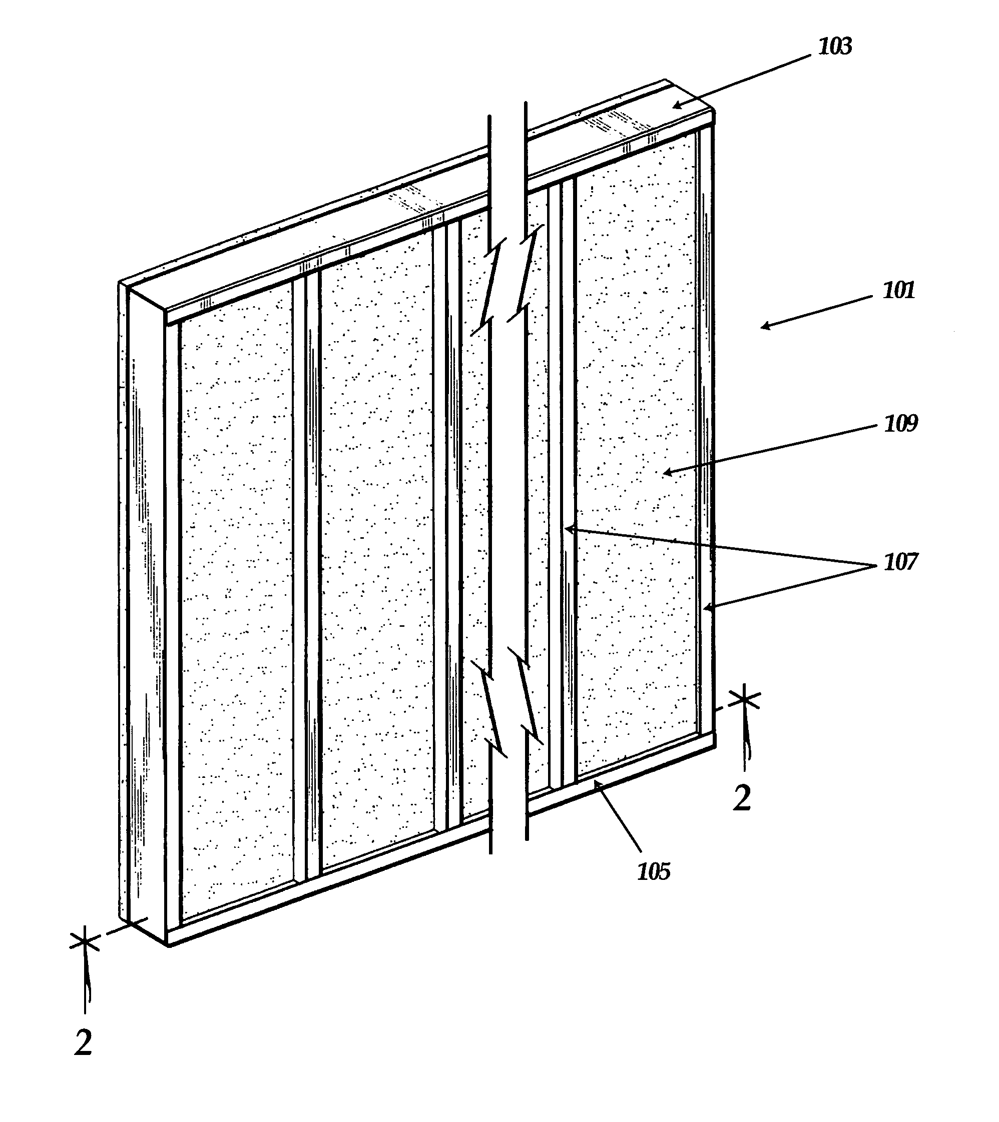
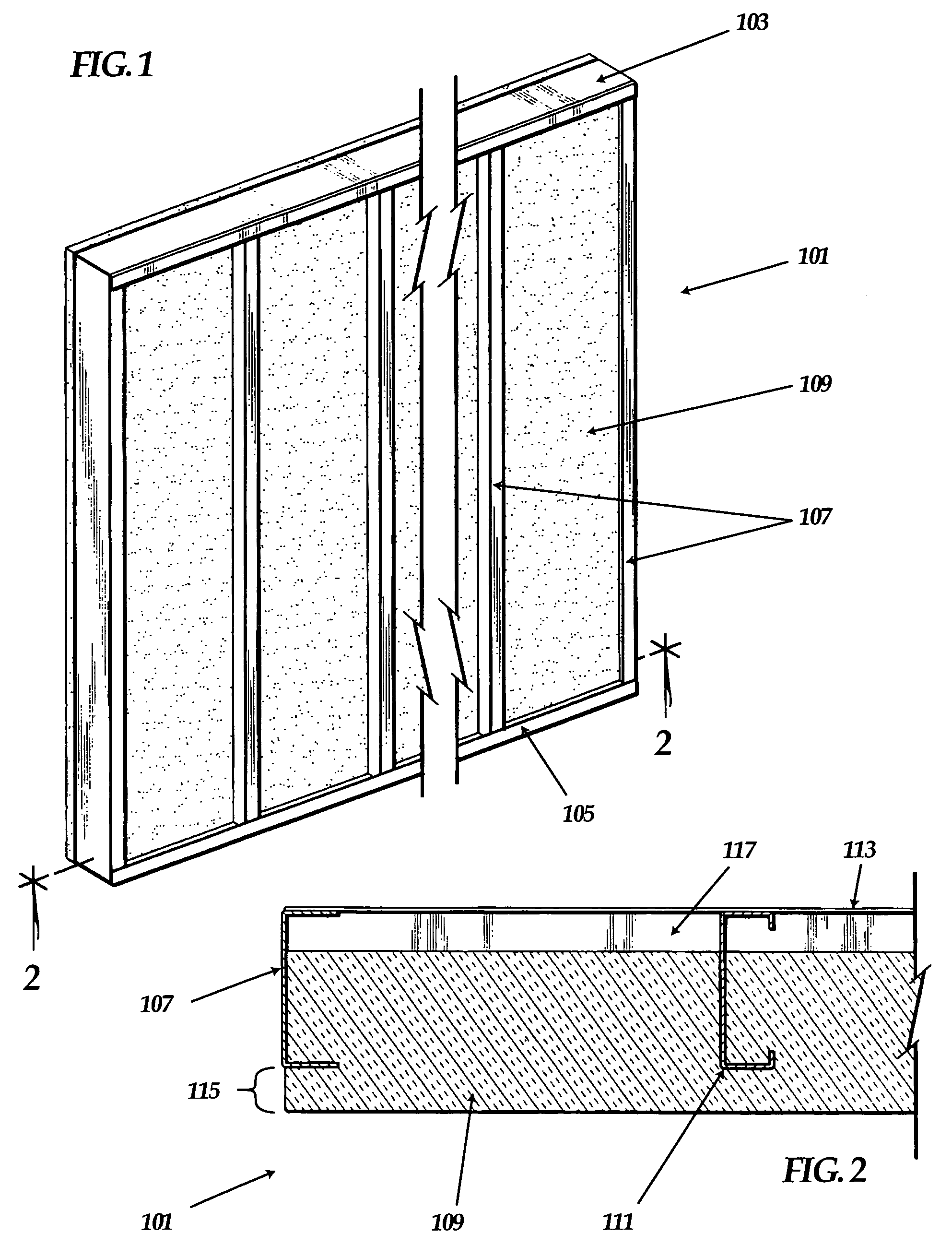
[0027]The invention as disclosed herein provides a novel apparatus and method for constructing prefabricated foam panels for use in construction. As shown in FIGS. 1 and 2, foam panel 101 has four main components: top frame 103, bottom frame 105, one or more studs 107, and foam block 109. Studs 107 are inserted into kerfs 111 in foam block 109, such kerfs having a substantially similar cross-sectional shape as studs 107. Top frame 103 and bottom frame 105 are secured to studs 107 to form a strong, lightweight, insulated foam panel 101. Foam block 109 forms the exterior surface of foam panel 101. The interior of foam panel 101 is wallboard 113 or other like material such as drywall, fiberboard, or plywood, which is attached to studs 107 on the building site according to the specific architectural design of the building. In order to meet building codes of most locations, studs 107 must be recessed from the exterior of foam block 109 by a minimum predetermined depth 115. In most applic...


PUM

PropertyMeasurementUnit
depthaaaaaaaaaa
widthsaaaaaaaaaa
temperature coefficientaaaaaaaaaa

Abstract

An apparatus and associated method for constructing prefabricated foam panels is provided. While making a longitudinal pass over a foam block, the apparatus flattens the foam block, cuts longitudinal kerfs in the foam block, and draws metal studs into the kerfs. The apparatus comprises a unique, heated blade having a shape similar to the cross section of a metal stud. The blade kerfs foam blocks, including blocks made of recycled or low-grade foam. The associated method includes kerfing the foam blocks by passing the blade through the foam blocks and drawing metal studs into the kerfs.

Description

CROSS REFERENCES[0001]None.GOVERNMENTAL RIGHTS[0002]None.BACKGROUND OF THE INVENTION[0003]Historically, buildings were constructed out of natural resources that were readily and locally available, such as mud, wood, sod, or stone. These materials present a number of disadvantages, including relatively low structural integrity, the requirement of skilled artisans to assemble the materials, the lengthy amount of time involved in assembling the materials, and the need to independently insulate the building. Recently, builders developed updated building materials, including prefabricated building panels made of metal studs and foam insulation. The invention relates to improved methods of constructing prefabricated metal stud and foam panels.[0004]One type of foam panel is made by kerfing a block of foam using a hot wire cutter. As shown in U.S. Pat. No. 6,167,624, issued to Lanahan et al., hot wire cutters are machines that heat tensioned wires measuring slightly longer than the length ...

Claims


Application Information

Patent Timeline
Patent Type & Authority Patents(United States)
IPC IPC(8): B21D49/00E04G21/14
CPCB26D3/008B26F3/08B26D1/0006Y10T29/49632B26D2001/0053B26D3/10
Inventor COLE, KENNETH R.COLE, KEITH LEROYCOLE, JOHN RAY
Owner SYSTECO CAYMAN LTD SECZ
Why Eureka
Try Eureka