
Shaped feed-through element with contact rod soldered in

a contact rod and feed-through element technology, applied in the field of feed-through elements, can solve the problems of increased production cost, increased process cost due to the surface grinding of glass materials, and increased production cost, and achieve the effect of reducing production cost and system cos

Active Publication Date: 2013-03-19
SCHOTT AG
View PDF15 Cites 22 Cited by
  • Summary
  • Abstract
  • Description
  • Claims
  • Application Information

AI Technical Summary

Benefits of technology

The solution enables the production of feed-through elements that are mechanically stable, cost-efficient, and resistant to high explosive pressures, while reducing production costs and complexity, ensuring reliable operation in pyrotechnic devices.

Problems solved by technology

Disadvantages are the higher process costs due to the surface grinding of the glass material.
This, however, entails extra production costs.
This prevents visual inspection and therefore makes the required quality inspection during production more difficult.
Disadvantages are the larger area of glass, which weakens the design, as well as the more elaborate earthing and higher total costs of the system.
Both processes are time-consuming and therefore make production more expensive.
The fundamental problem with stamping support bodies, however, is that the access openings have to be stamped with great accuracy, particularly in respect of the diameter variance and the profile of the access opening.
In the event of the ignition, the entire explosive force acts on the glass, and it is therefore not mechanically stable enough.
The material costs of the NiFeCo alloy, however, are extremely high.
Owing to these disadvantages, this embodiment has not yet come into use.
This embodiment also suffers from the disadvantage that the support body conventionally consists of a stainless steel, because otherwise the support body made of a non-stainless metal would need to be coated in order to avoid corrosion.
In the case of such coated support bodies, however, the glass surface of the glass-metal feed-through can then no longer be ground because otherwise the coating would be abraded as well.
The costs for production furthermore are increased by grinding and polishing the glass surface of the one glass-metal feed-through, by welding the bridging wire and the process outlay for producing the large-area soldering of the earth pin onto the support body.

Method used


Image

  • Shaped feed-through element with contact rod soldered in
  • Shaped feed-through element with contact rod soldered in
  • Shaped feed-through element with contact rod soldered in

Examples


Embodiment Construction

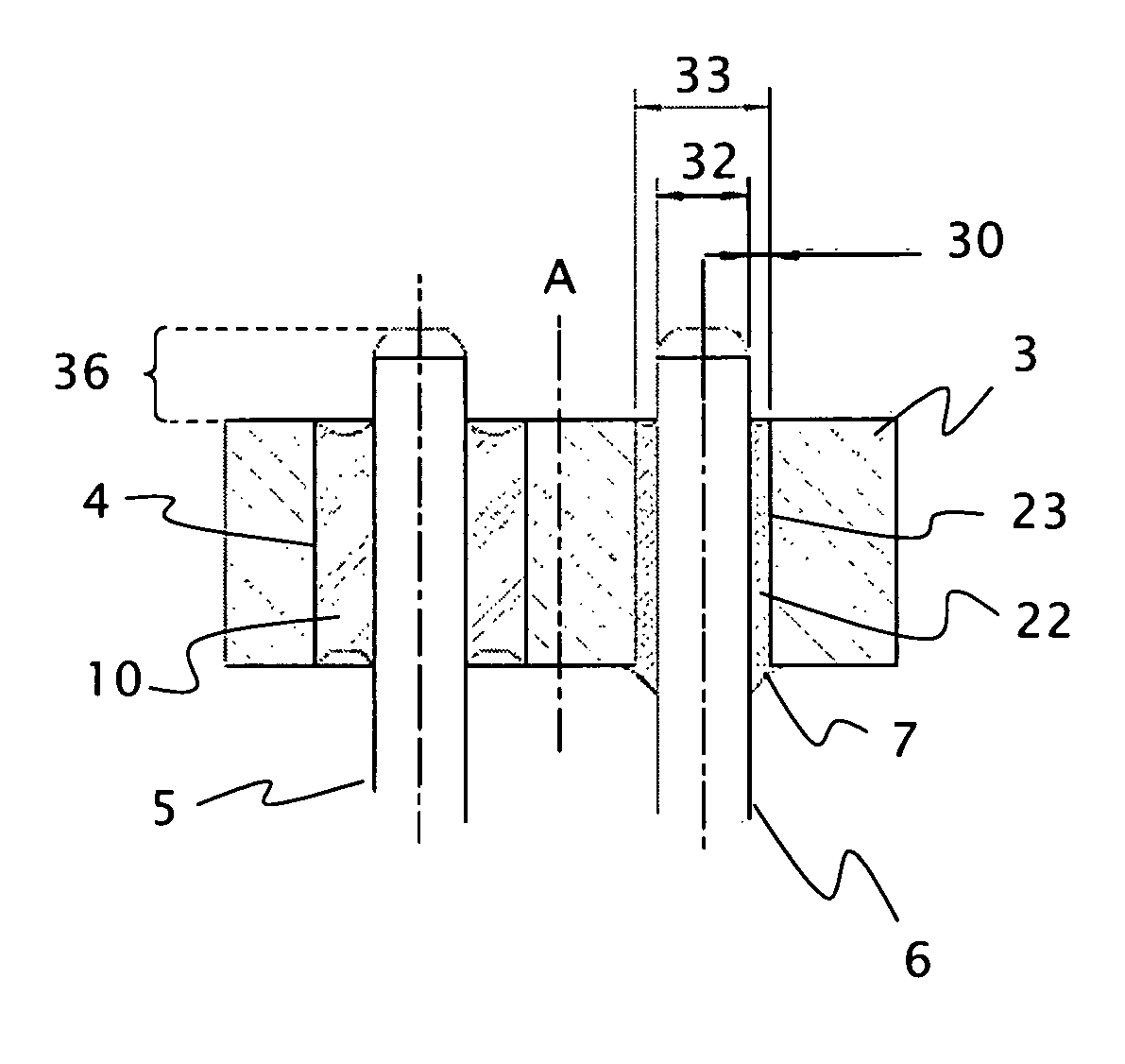
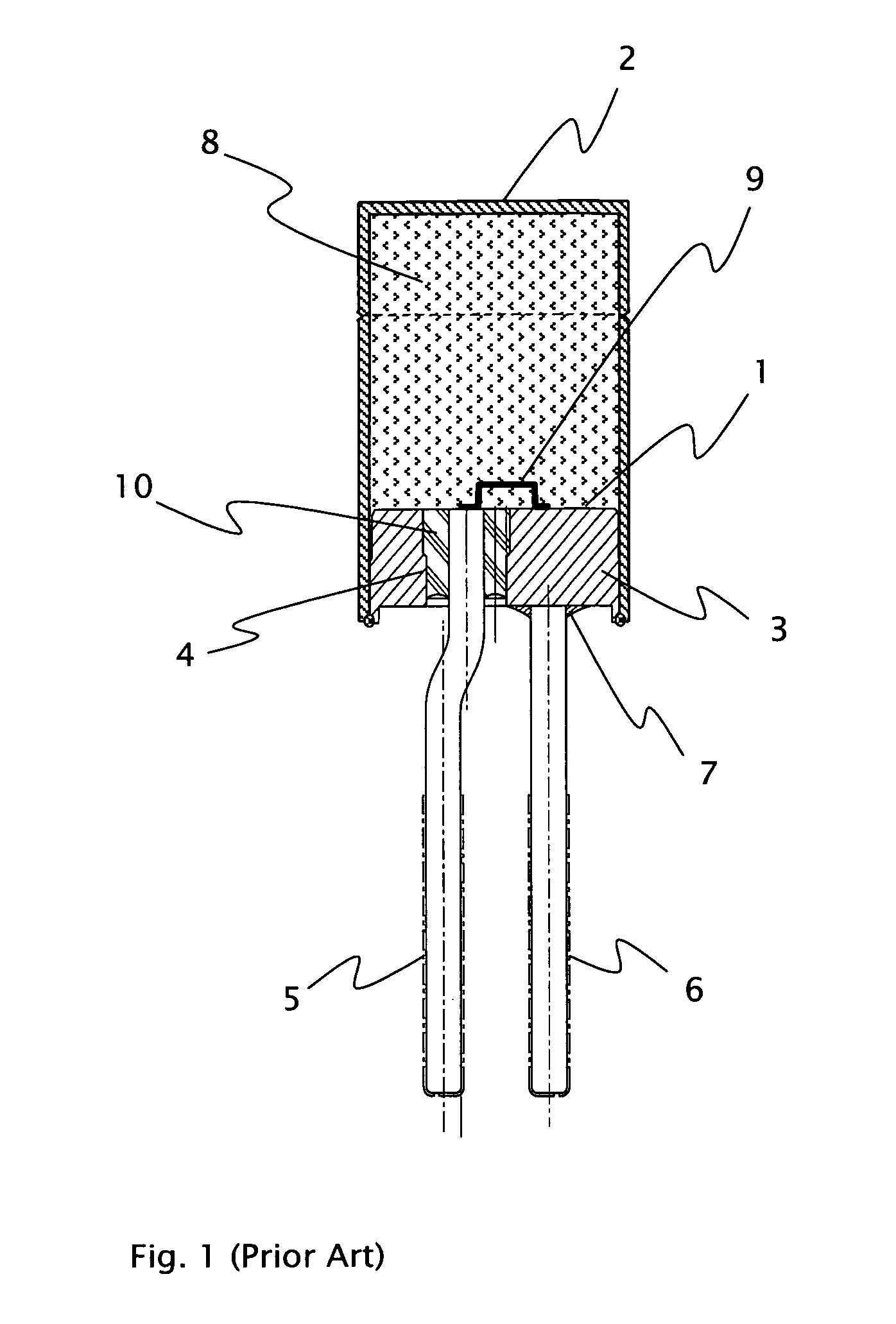
[0072]FIG. 1 represents a known ignition device for a pyrotechnic protection device according to the prior art. FIG. 1 shows in particular a sectional view of the feed-through element (1).

[0073]The feed-through element (1) comprises a shaped metal carrier part having a support body (3), which has a disc-shaped base shape. The feed-through element (1) is often also referred to as a base element or base for short. In order to avoid corrosion or reaction with the propellant charge, stainless steel is used as the material for the support body (3) in this ignition device, even though this material is more difficult to shape than many other metals.

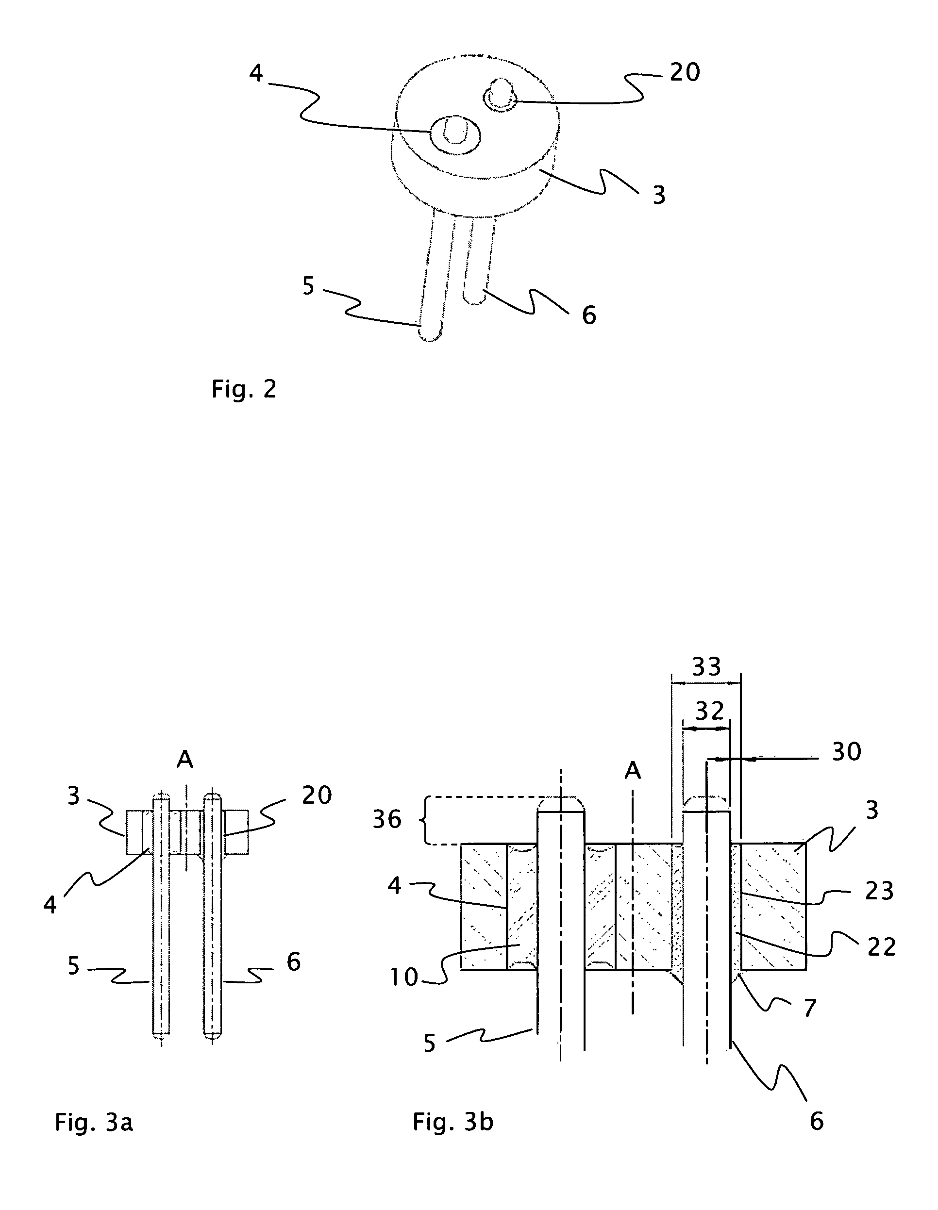
[0074]In a first access opening (4) of the support body (3), a metal rod (5) is furthermore arranged as a pin. The access opening (4) has in this case been stamped from the support body (3). This likewise applies for the outer contour of the support body (3). In other embodiments, this access opening is drilled.

[0075]The metal rod (5) is used fo...


PUM

PropertyMeasurementUnit
diameteraaaaaaaaaa
widthaaaaaaaaaa
widthaaaaaaaaaa

Abstract

A feed-through element of an ignition device for igniters of airbags or seatbelt tighteners is provided. The feed-through element has a metal support body, at least one first access opening in which a metal rod is arranged in an electrically insulating fixing material, and at least one second access opening in which a further metal rod is electrically conductively fixed to the support body by a soldered connection in this access opening. The support body and the access openings are configured as a shaped part. The feed-through element further includes a solder gap between the metal rod and the wall of the second access opening, where the solder gap has a small width.

Description

CROSS REFERENCE TO RELATED APPLICATIONS[0001]This application claims benefit under 35 U.S.C.§119(a) of German Patent Application No. 10 2009 008 673.0-21, filed Feb. 12, 2009, the entire contents of which are incorporated herein by reference.BACKGROUND OF THE INVENTION[0002]1. Field of the Invention[0003]The present disclosure relates to feed-through elements in general, but in particular those for ignition devices such as are used to ignite a pyrotechnic person protection device. In particular, the present disclosure relates to the configuration of the base of such an ignition device.[0004]2. Description of Related Art[0005]In particular, airbags and seatbelt tensioners are used as person protection devices in motor vehicles. Such safety systems can significantly reduce the risk of injury. A prerequisite, however, is that the safety systems in question do not fail in the event of a collision. Particular attention is paid to the igniters of such pyrotechnic apparatus, which are indi...

Claims


Application Information

Patent Timeline
Patent Type & Authority Patents(United States)
IPC IPC(8): F42B3/10F42B3/04B23K31/02
CPCF42B3/107F42B3/103
Inventor FINK, THOMASRANFTL, REINHARD
Owner SCHOTT AG
Learn More