Electrical connectors for photovoltaic systems

a technology of photovoltaic systems and electrical connectors, applied in the direction of couplings/cases, coupling device connections, electrical apparatus, etc., can solve the problems of non-sealing of internal seals, and achieve the effect of convenient and complete plug insertion

Active Publication Date: 2013-03-19
HEYCO
View PDF16 Cites 20 Cited by
  • Summary
  • Abstract
  • Description
  • Claims
  • Application Information

AI Technical Summary

Benefits of technology

[0006]Both the inner wall of the socket of the first connector member and the outer wall of the plug of the second connector member are closely mated to each other and have smooth, generally conical and tapered surfaces to allow easy and complete insertion of the plug into the socket and separation thereof. When the plug of the second connector member has been completely inserted into the socket of the first connector member, the tip of the plug contacts (or at least is within close proximity to) the annular ring at the base of the socket, which is deformed so as to form a water-tight seal between the tip of the plug and the base of the socket. Likewise, the annular ring at the tip of the socket contacts (or at least is within close proximity to) the base of the recess and is deformed so as to form another water-tight seal between the tip of the socket and the base of the recess. These water-tight seals protect the electrically conductive components from moisture infiltration when the first and second connector members are mated with one another. A resilient deformable material or other sealing material, or an auxiliary seal, such as an o-ring, may also be used to add to the sealing effect.
[0007]A locking mechanism can be provided that locks the first and second connector members together when the plug of the second connector member is completely inserted into the socket of the first connector member, so as to insure the efficacy of the sealing effect. Specifically, the first connector member includes locking windows penetrating its outer collar, and the second connector member includes flexible locking tabs formed in its outer collar. The windows and tabs are arranged such that each tab engages with a respective window only when the plug has been completely inserted into the socket. In the locked configuration, each tab is recessed into its respective window, such that a tool is required to disengage it. As a result, the first and second connector members are prevented from any significant rotation with respect to each other, which might cause internally formed seals to be non-sealing.

Problems solved by technology

As a result, the first and second connector members are prevented from any significant rotation with respect to each other, which might cause internally formed seals to be non-sealing.

Method used


Image

  • Electrical connectors for photovoltaic systems
  • Electrical connectors for photovoltaic systems
  • Electrical connectors for photovoltaic systems

Examples


Embodiment Construction

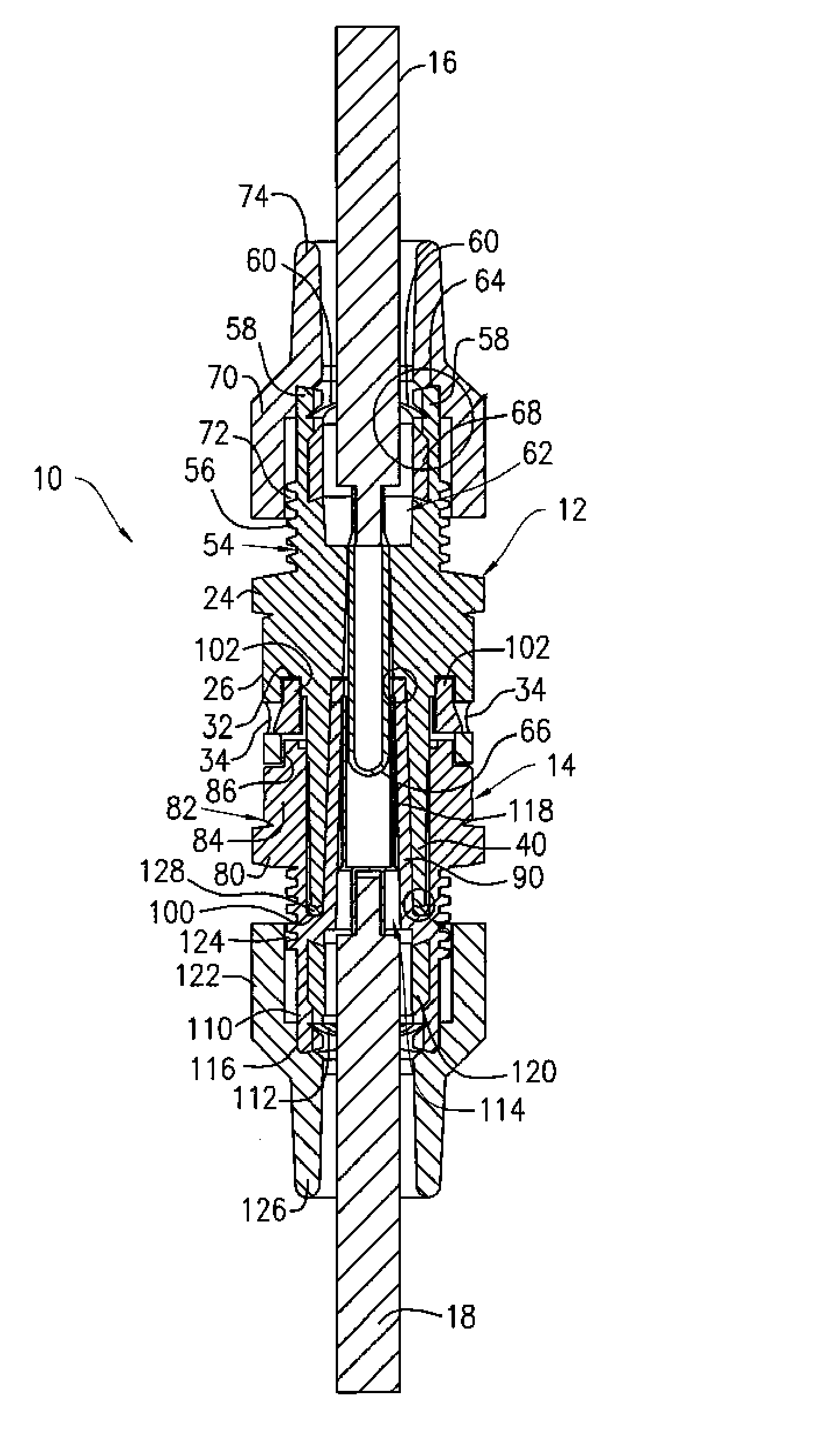
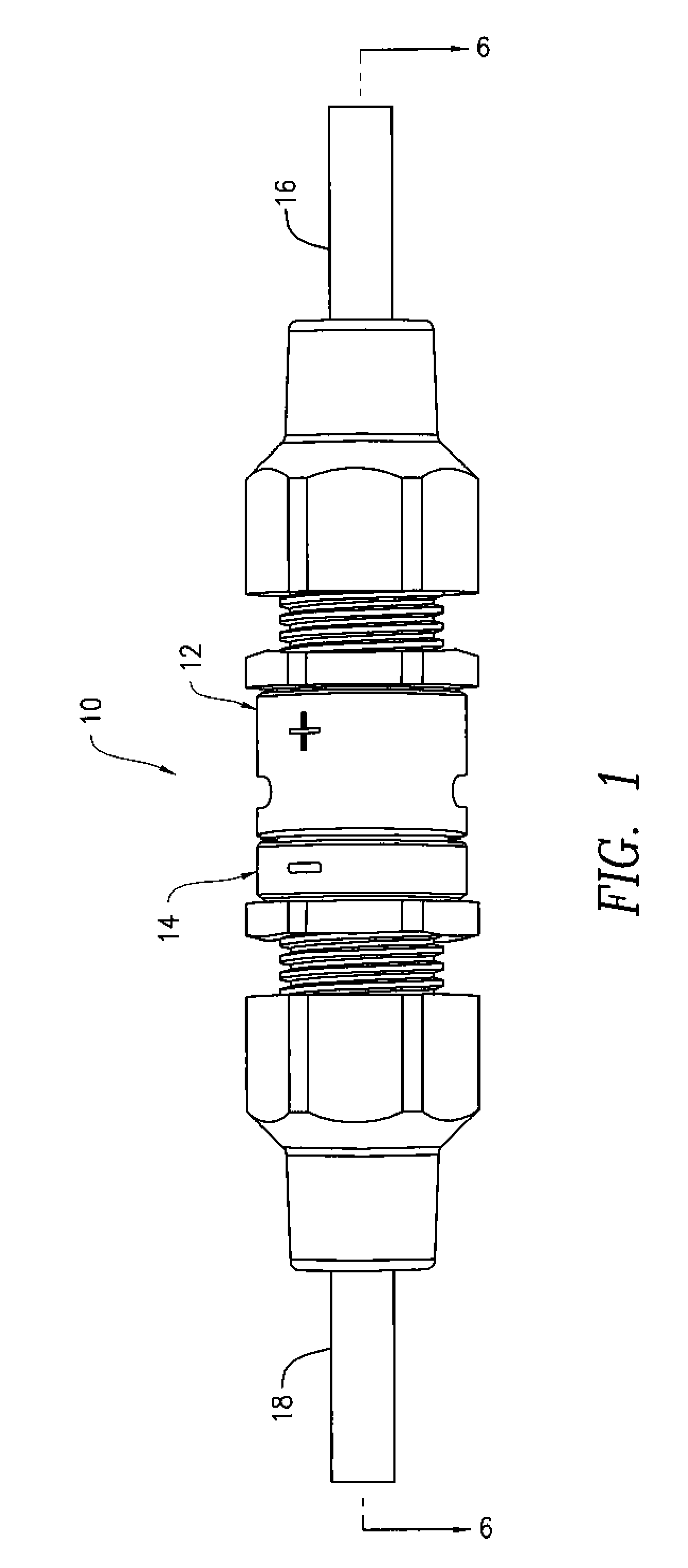
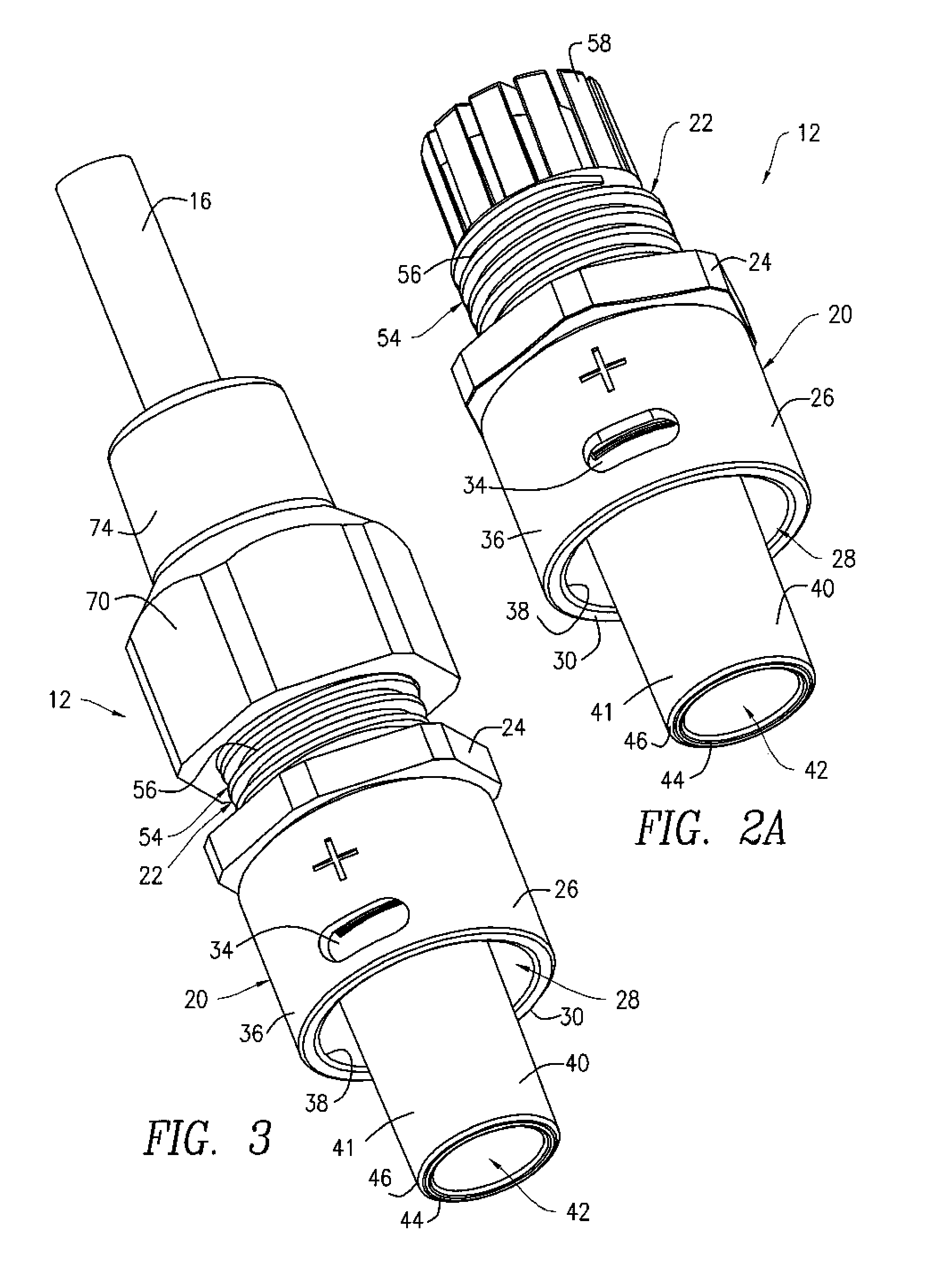
[0023]Referring to FIG. 1, an electrical connector system 10 includes a first connector member 12 and a second connector member 14 releasably mated with the first connector member 12. The first connector member 12 is attached to a first electrical conductor 16, such as a first electrical wire, while the second connector member 14 is attached to a second electrical conductor 18, such as a second electrical wire. When mated, the first and second connector members 12, 14 provide a physical and an electrical connection between the first and second electrical conductors 16, 18.

[0024]The first and second connector members 12, 14 can be manufactured from a thermoplastic polymer, such as polycarbonate. Alternatively, the first and second connector members 12, 14 may be manufactured from any other suitable materials known in the art, especially materials having electrical insulating properties and adequate flexibility, and the materials can be supplied by other manufacturers. Each of the fir...


PUM


Abstract

An electrical connector system including first and second electrical connector members mated to one another to form a sealed connection in order to protect electrically-conductive components against the infiltration of moisture. The first connector member includes a socket with a first annular ridge at its tip, while a second annular ridge is formed within the socket at its base. An electrically-conductive pin is housed within the first connector member and extends into the interior of the socket. The second connector member includes a plug. An electrically-conductive socket, mated to the pin, is housed within the plug. When the plug of the second connector member is mated with the socket of the first connector member, the tip of the plug contacts the annular ridge at the base of the socket, which is deformed so as to form a water-tight seal between the tip of the plug and the base of the socket. Likewise, the annular ridge at the tip of the socket contacts the base of the recess and is deformed so as to form another water-tight seal between the tip of the socket and the base of the recess.

Description

CROSS-REFERENCE TO RELATED APPLICATION[0001]This application is a Section 111(a) application relating to commonly owned, co-pending U.S. Provisional Patent Application No. 61 / 254,770, entitled ELECTRICAL CONNECTORS FOR PHOTOVOLTAIC SYSTEMS, filed on Oct. 26, 2009, the disclosure of which is incorporated by reference herein.FIELD OF THE INVENTION[0002]The disclosed subject matter relates to electrical connectors and, more particularly, electrical connectors for use in connection with photovoltaic systems.BACKGROUND OF THE INVENTION[0003]There is a growing need for renewable energy sources, with solar energy being at the forefront. As a result, the use of photovoltaic systems has increased exponentially in recent years. Electrical connectors are an integral part of a photovoltaic system, as they provide the necessary electrical connections between individual solar panels (i.e., photovoltaic modules) of a solar array, typically via electrical junction boxes, and between the solar panel...

Claims


Application Information

Patent Timeline
Patent Type & Authority Patents(United States)
IPC IPC(8): H01R13/52
CPCH01R13/5219H01R13/59H01R13/6273
Inventor COYLE, JR., WILLIAM J.
Owner HEYCO
Why Eureka
Try Eureka