Thermal processing furnace and liner for the same

a technology of thermal processing furnace and liner, which is applied in the direction of furnace electric heating, chemical vapor deposition coating, pressure vessel for chemical process, etc., can solve the problems of significant temperature gradients within the reaction chamber, unrecognized causes of contamination of the reaction chamber atmosphere, and inability to prevent the backflow of deposits, etc., to facilitate particle transport and mitigate the problem of backflow

Active Publication Date: 2013-03-19
ASM INTERNATIONAL
View PDF12 Cites 336 Cited by
  • Summary
  • Abstract
  • Description
  • Claims
  • Application Information

AI Technical Summary

Benefits of technology

[0010]In itself the deposition of by-products adjacent the downstream end of the gas exhaust path, i.e. on the flange and in the gas exhaust conduit, does not cause contamination of the reaction chamber. It seems, however, that material deposited at the downstream end of the gas exhaust path may be whirled up and transported back, through the gas passage, into the reaction chamber by recirculating gas flows. During normal operation of a thermal processing furnace such recirculating gas flows are unlikely to occur, both because of the low pressure at which processes are typically carried out and the pressure gradient along the gas exhaust path that is imposed and maintained by the vacuum pump. There are situations, however, during which these factors do not prevent the backflow of deposit. For instance, when, after discharging one wafer boat holding processed wafers from the reaction chamber another wafer boat with a fresh batch of wafers is being loaded into the reaction chamber, the reaction chamber may be at atmospheric pressure and the vacuum pumps may be temporarily switched off. The introduction of the new, relatively cold wafer boat with the likewise cold unprocessed wafers into the relatively warm reaction chamber may cause significant temperature gradients within the reaction chamber, in particular between the outer reaction tube, the liner and the wafer boat. These temperature gradients may induce pressure gradients, which may in turn drive convective flows over the liner. These flows may facilitate particle transport from the downstream end of the exhaust path, via the gas passage, back into the reactor chamber. This way, particles may end up on the wafers, in particular those near the top of the wafer boat.
[0011]It an object of the present invention to provide for a thermal processing furnace in which the above-mentioned problem of backflow of material that has been deposited at the downstream end of the gas exhaust path is overcome or mitigated.
[0012]It is another object of the present invention to provide for a liner that may be installed in a conventional thermal processing furnace (possibly as a replacement for the originally installed liner) so as to overcome or mitigate the problem of backflow of material deposited near the downstream end of the gas exhaust path.
[0018]In yet another embodiment, the flow deflector may extend along, or be distributed over, the axial length of the inner reaction tube, such that the flow deflector extends (i.e. is present) in all of three equally long axially extending portions of the gas passage that together cover a total length thereof. Such distribution or spreading of the flow deflector over the axial length of the gas passage helps to minimize the size of axial gas passage portions in which strong, upwardly directed gas flows may develop in the absence of by the flow deflector.

Problems solved by technology

Research by applicant to further improve the performance of her thermal processing furnaces has revealed that another, yet unrecognized cause of contamination of the reaction chamber atmosphere exists.
The source of the contamination appears to lie partly in the fact that process gases tend to form a deposit when they are being exhausted via the relatively cold lower portion of the furnace, which includes the flange and the gas exhaust conduit.
There are situations, however, during which these factors do not prevent the backflow of deposit.
The introduction of the new, relatively cold wafer boat with the likewise cold unprocessed wafers into the relatively warm reaction chamber may cause significant temperature gradients within the reaction chamber, in particular between the outer reaction tube, the liner and the wafer boat.

Method used


Image

  • Thermal processing furnace and liner for the same
  • Thermal processing furnace and liner for the same
  • Thermal processing furnace and liner for the same

Examples


Embodiment Construction

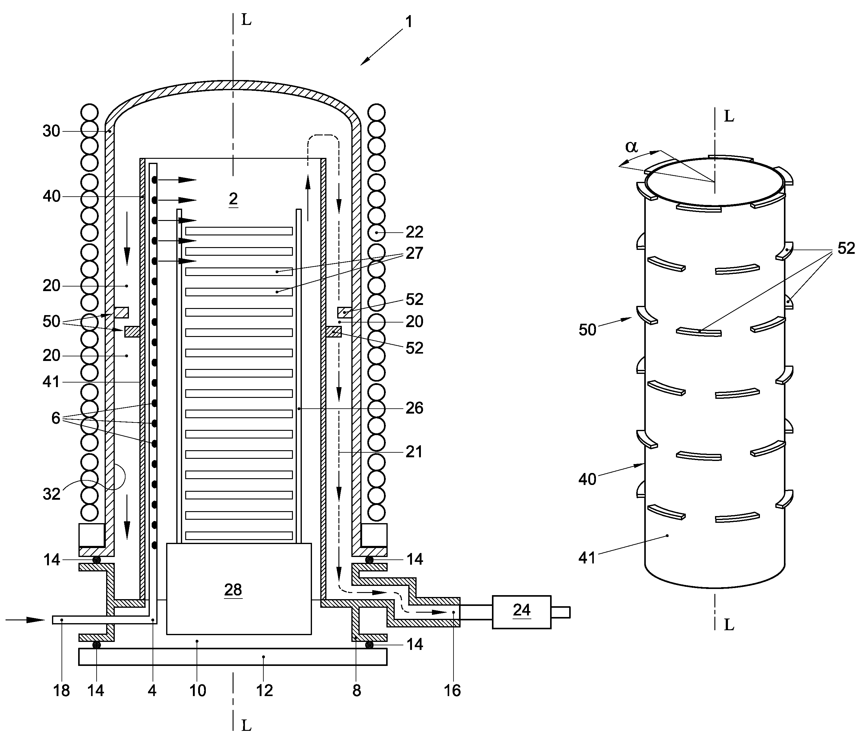
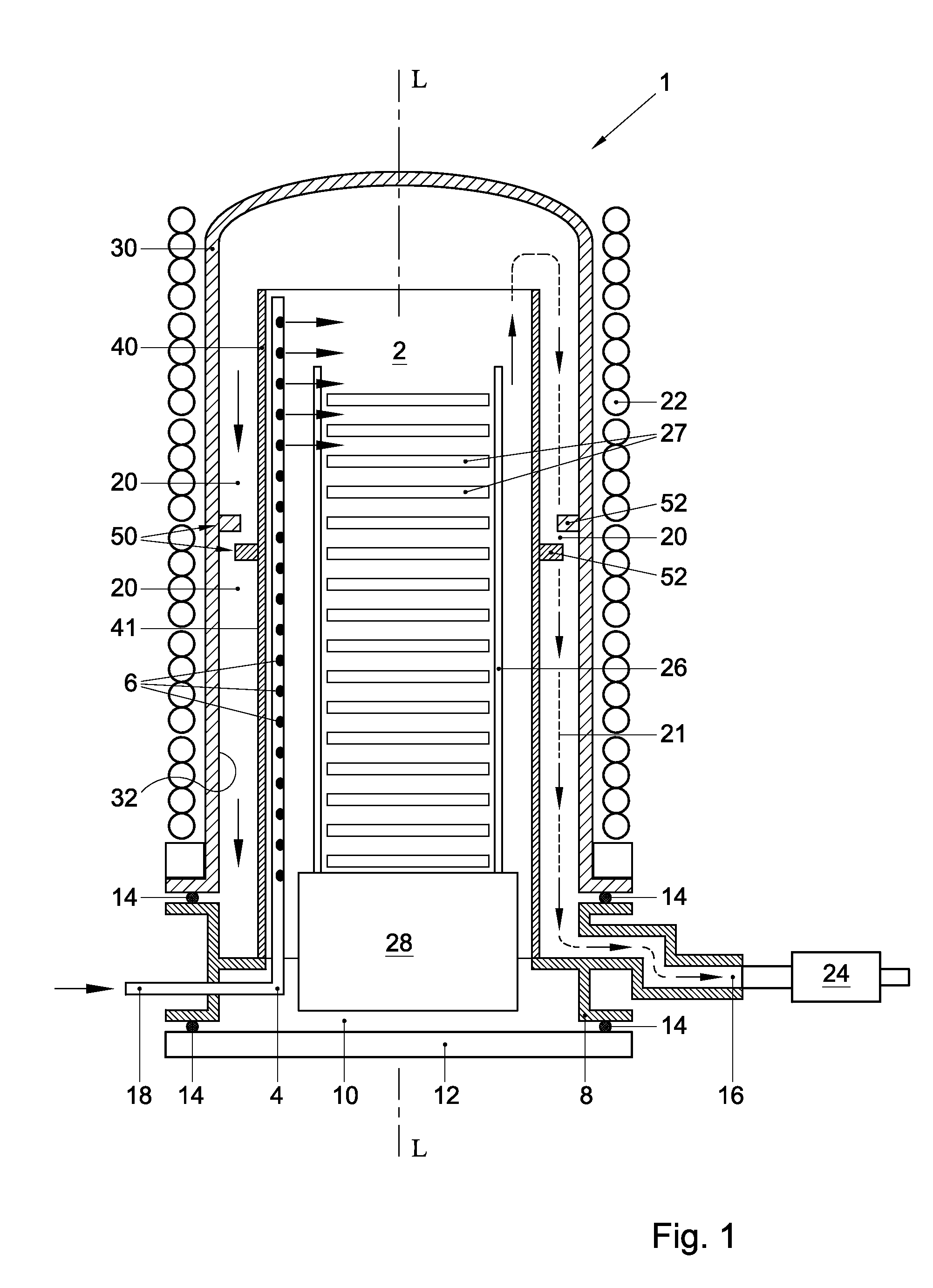
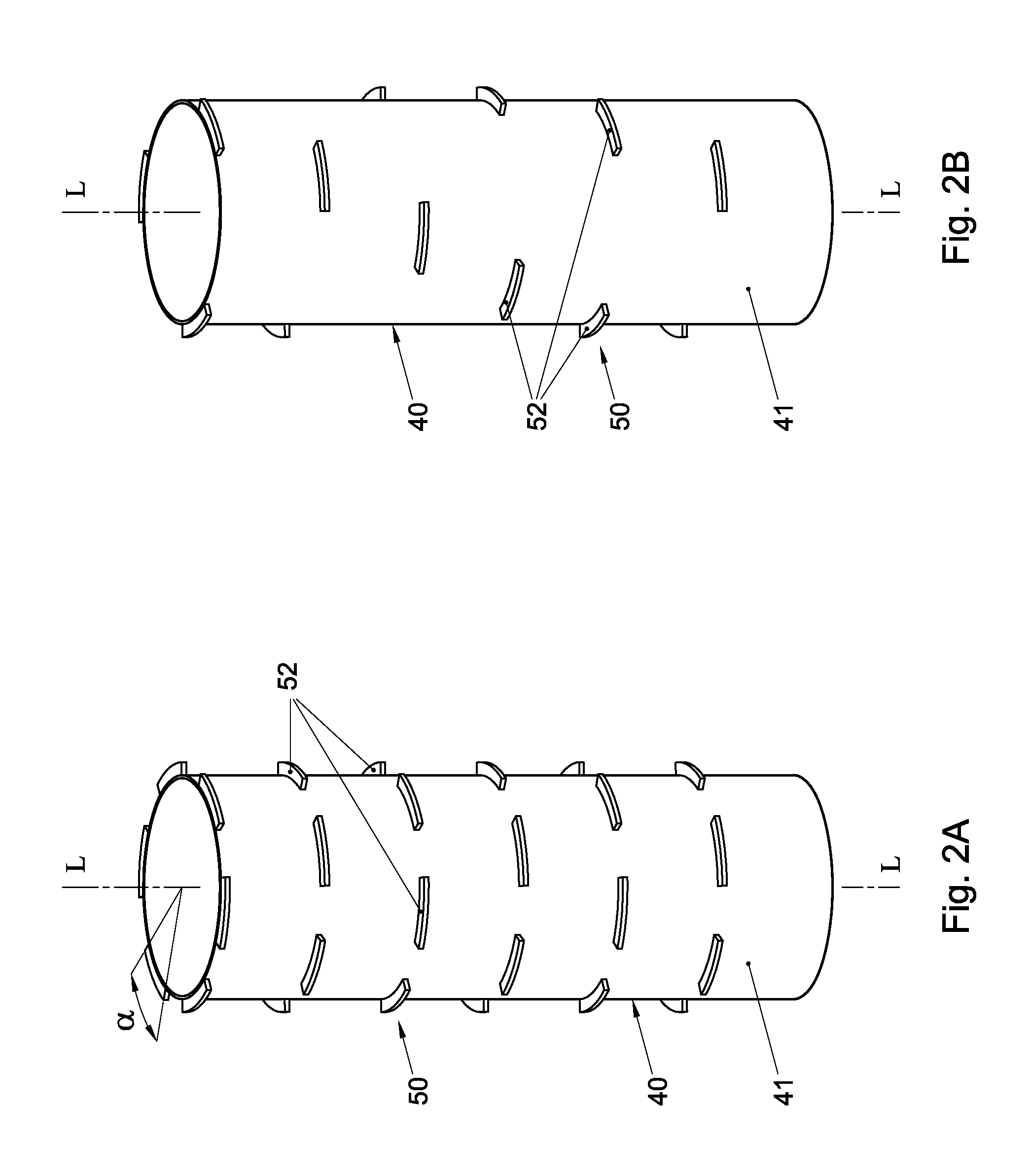
[0023]FIG. 1 schematically illustrates in a cross-sectional side view an exemplary vertical thermal processing furnace or reactor 1 according to the present invention. The furnace 1 is of a double tube type, and includes a generally bell jar-shaped outer reaction tube 30 and an open-ended inner reaction tube 40. The inner reaction tube 40 may alternatively be referred to as the liner. The outer reaction tube 30 may be surrounded by heating means, such as a thermally resistive heating coil 22 that is powered by an electrical power supply (not shown). The heating means may further be secured to a thermally insulating sleeve (not shown) that surrounds the outer reaction tube 30. Both reaction tubes 30, 40 may have a generally tubular, for example circular or polygonal, cross-sectional shape. An outer diameter of the inner tube 40 may be smaller than an inner diameter of the outer reaction tube 30. Accordingly, the inner reaction tube 40 may be at least partially disposed within the out...


PUM

PropertyMeasurementUnit
widthaaaaaaaaaa
widthaaaaaaaaaa
widthaaaaaaaaaa

Abstract

A thermal processing furnace, comprising:a generally bell jar-shaped outer reaction tube having a central axis; andan open-ended inner reaction tube for accommodating a wafer boat holding a plurality of substrates, which inner reaction tube is substantially coaxially disposed within the outer reaction tube, thereby defining a gas passage between an outer wall of the inner reaction tube and an inner wall of the outer reaction tube,wherein at least one of the outer wall of the inner reaction tube and the inner wall of the outer reaction tube is provided with a flow deflector that protrudes radially from the respective wall into the gas passage.

Description

FIELD OF THE INVENTION[0001]The present invention generally relates to equipment for processing semiconductor substrates, and more in particular to a vertical thermal processing furnace and a liner for use therein.BACKGROUND[0002]Thermal processing furnaces or reactors are commonly used for batch processing semiconductor wafers during several fabrication stages of silicon integrated circuits. Processing steps for which a furnace may be used include oxidation, diffusion, annealing and chemical vapor deposition (CVD) and pulsed atomic layer deposition (ALD).[0003]A conventional vertical thermal processing furnace may include a thermally resistive heating coil, powered by an electrical power supply. Within the heating coil there may be provided a bell jar-shaped outer reaction tube and an inner reaction tube that is coaxially disposed within the outer reaction tube. The inner reaction tube is commonly referred to as the liner. The lower end of the outer reaction tube may be open, while...

Claims


Application Information

Patent Timeline
Patent Type & Authority Patents(United States)
IPC IPC(8): C23C16/00C23C16/455
CPCH01L21/67109
Inventor JDIRA, LUCIAN C.ADJEROUD, NOUREDDINE
Owner ASM INTERNATIONAL
Why Eureka
Try Eureka