
Radiation detector

a radiation detector and detector technology, applied in the field of radiation detectors, can solve the problems of affecting the detection accuracy of radiological hazards, the gradual blurring of radiation dose patterns, and the loss of spatial resolution, and the techniques of the prior art suffer, and many systems, and particularly those associated with radiation therapy applications, demonstrate an inability to perform in high radiation background

Inactive Publication Date: 2013-03-19
NEXIA SOLUTIONS
View PDF9 Cites 0 Cited by
  • Summary
  • Abstract
  • Description
  • Claims
  • Application Information

AI Technical Summary

Benefits of technology

The device provides accurate, three-dimensional mapping of radiation hazards in high radiation environments, is cost-effective, and can be deployed in confined spaces without electrical power, offering improved safety and operational efficiency.

Problems solved by technology

However, such techniques suffer from a major disadvantage that is intrinsic to the Fricke gel medium, wherein ferric ions are able to diffuse quite freely through the gel after irradiation, thereby leading to a gradual blurring of the radiation dose pattern and a consequent loss of spatial resolution.
The techniques of the prior art do, however, suffer from several disadvantages.
For example, many systems—and particularly those associated with radiation therapy applications—demonstrate an inability to perform in high radiation backgrounds.
Other common difficulties include practical problems in deployment, due to physical spatial constraints or the remoteness of locations in which investigations are to be performed.
Furthermore, cost issues are often highly significant, with systems such as thee Radscan® 800 typically being expensive to purchase.

Method used


Image

  • Radiation detector
  • Radiation detector
  • Radiation detector

Examples


Embodiment Construction

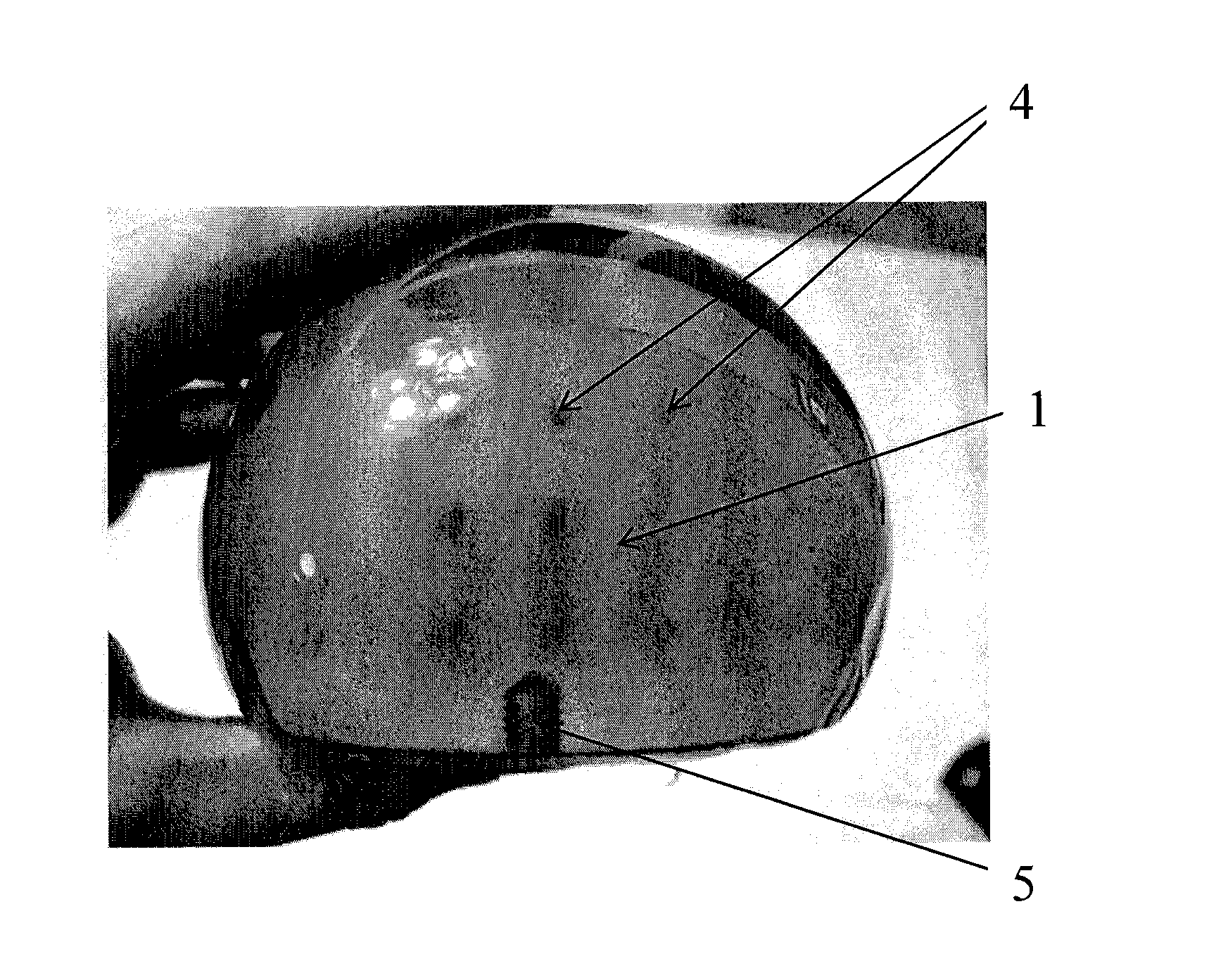
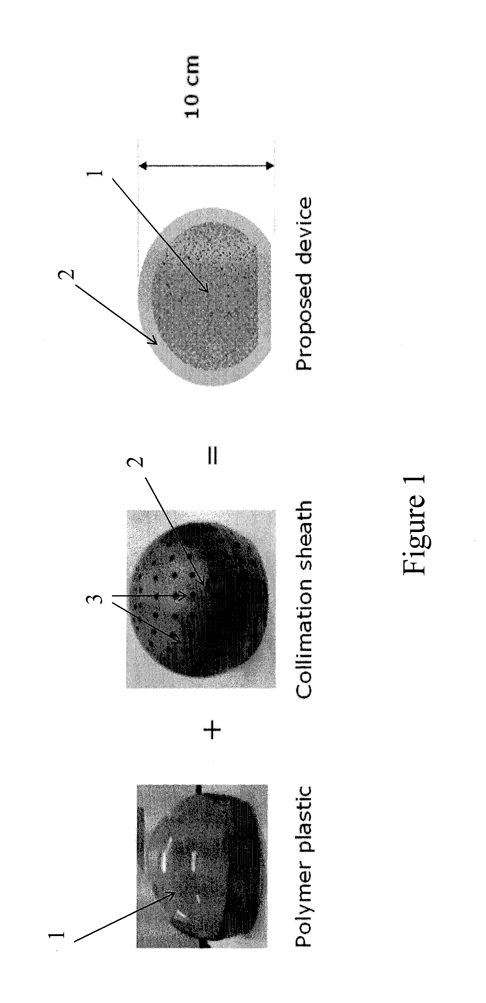
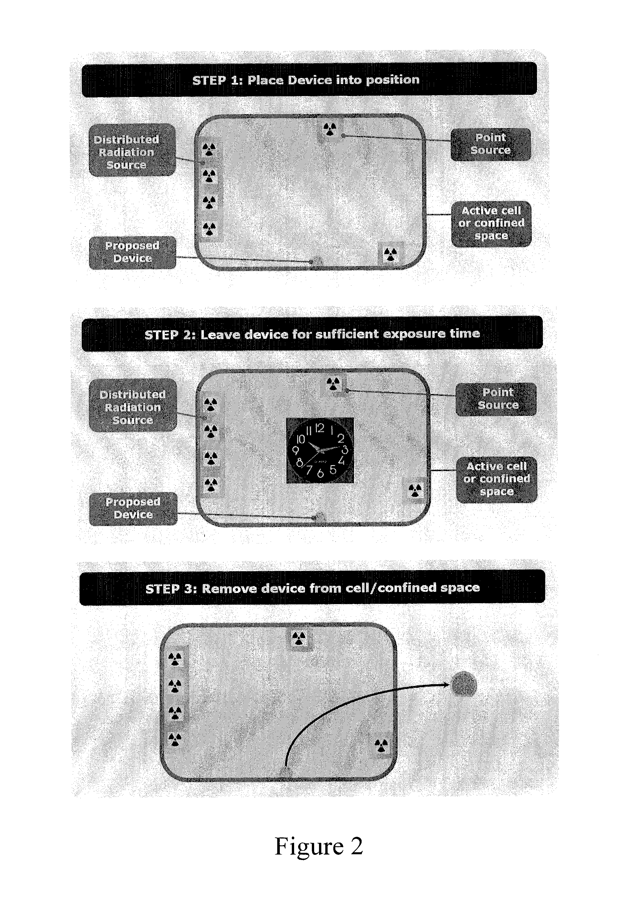
[0030]The device of the present invention is based on a polymeric core material comprising at least one radiation sensitive material which is located within an external shall material comprising a collimation sheath. The device and method of the invention facilitate the detection and mapping of radiation, and find particular use in mapping the location, intensity and identity of radiological hazards in 3 dimensions in sites such as active cells, gloveboxes, other active plants and confined spaces.

[0031]The device typically has a truncated spherical shape and a diameter in the region of 5-20 cm, most conveniently around 10 cm. A basic spherical shape has been shown to provide the most satisfactory and efficient embodiment of the invention, and the truncated spherical shape has the advantage that it allows for the device, in operation, to be placed on a flat surface. In the event that the device is to be suspended in space, a perfect spherical shape may, of course, be employed. For an...


PUM

PropertyMeasurementUnit
diameteraaaaaaaaaa
thicknessaaaaaaaaaa
cross-sectional areaaaaaaaaaaa

Abstract

The invention provides a device for the detection and mapping of radiation, the device comprising a polymeric core located within an external shell material, wherein the polymeric core comprises at least one radiation sensitive component and the external sheath comprises a collimation sheath. Preferably, the polymeric core comprises a spherical core which is encased within the external shell. The external shell is preferably comprised of a metal, most preferably lead or tungsten. The invention also provides a method for the detection and mapping of radiation in a location, which comprises: (a) placing a device according to the invention in the location to be investigated; (b) allowing the device to remain in the location and be exposed to the radiation for a predetermined length of time; (c) removing the device from the location; (d) removing the polymeric core from the external shell; and (e) analysing said polymeric core by means of an optical analysis technique applying a software-based image reconstruction algorithm in order to determine the location, form and intensity of said radiation. The device and method of the invention facilitate the detection and mapping of radiation, and find particular use in mapping the location, intensity and identity of radio-logical hazards in 3 dimensions in sites such as active cells, gloveboxes, other active plants and confined spaces. Advantages over the prior art include the lack of requirement for an electrical supply, and the ability to deal with high radiation backgrounds and to be deployed in confined or restricted spaces.

Description

CROSS-REFERENCE TO RELATED APPLICATIONS[0001]This application is filed under the provisions of 35 U.S.C. §371 and claims the priority of International Patent Application No. PCT / GB2008 / 051066 filed on Nov. 14, 2008, which in turn claims priority of Great Britain Application No. 0722416.5 filed on Nov. 15, 2007, the contents of which are incorporated by reference herein for all purposes.FIELD OF THE INVENTION[0002]The present invention is concerned with the detection and mapping of radiological hazards. More specifically, it relates to a novel device that facilitates mapping of the location, intensity and identity of radiological hazards.BACKGROUND TO THE INVENTION[0003]Numerous applications exist for techniques which are capable of detecting and accurately measuring the presence of radiation and, more specifically, which have the facility for measuring and mapping radiation dose distributions in three dimensions with high spatial resolution. Such techniques find application in, for ...

Claims


Application Information

Patent Timeline
Patent Type & Authority Patents(United States)
IPC IPC(8): G01N21/00
CPCG01T1/08G01T7/00G01T5/10G01T1/06G01T1/161G01T1/2914
Inventor STANLEY, STEVEN JOHNDORAN, SIMON JOHNJENNESON, PAUL MICHAEL
Owner NEXIA SOLUTIONS
Learn More