
Turbine engine including an improved means for adjusting the flow rate of a cooling air flow sampled at the output of a high-pressure compressor using an annular air injection channel

a turbine engine and annular air technology, applied in the direction of machines/engines, sustainable transportation, mechanical equipment, etc., can solve the problems of reducing the performance of those turbine engines, affecting the efficiency of the turbine engine, and affecting the cooling air flow of the vanes. , to achieve the effect of simple, economical and effectiv

Active Publication Date: 2013-03-26
SN DETUDE & DE CONSTR DE MOTEURS DAVIATION S N E C M A
View PDF18 Cites 14 Cited by
  • Summary
  • Abstract
  • Description
  • Claims
  • Application Information

AI Technical Summary

Benefits of technology

The invention aims to address issues with high-pressure compressor cooling air flow in turbine engines. The goal is to reduce the flow rate of the cooling air to a normal level. This solution is expected to be simple, cost-effective, and effective in solving the problems.

Problems solved by technology

This can in particular result from excessive play between the rotary portion and the static portion of the aforementioned labyrinth seal, which can in particular occur during a change in the operating rating of the turbine engine.
Part of the flow delivered by the high-pressure compressor is then pointlessly sampled on the primary flow, which considerably reduces the performance of those turbine engines.
The mixture of the two aforementioned flows therefore causes a harmful increase in the temperature of the cooling air flow of the vanes, and even more so as the flow rate of the cooling air flow of the impeller is higher.

Method used


Image

  • Turbine engine including an improved means for adjusting the flow rate of a cooling air flow sampled at the output of a high-pressure compressor using an annular air injection channel
  • Turbine engine including an improved means for adjusting the flow rate of a cooling air flow sampled at the output of a high-pressure compressor using an annular air injection channel
  • Turbine engine including an improved means for adjusting the flow rate of a cooling air flow sampled at the output of a high-pressure compressor using an annular air injection channel

Examples


Embodiment Construction

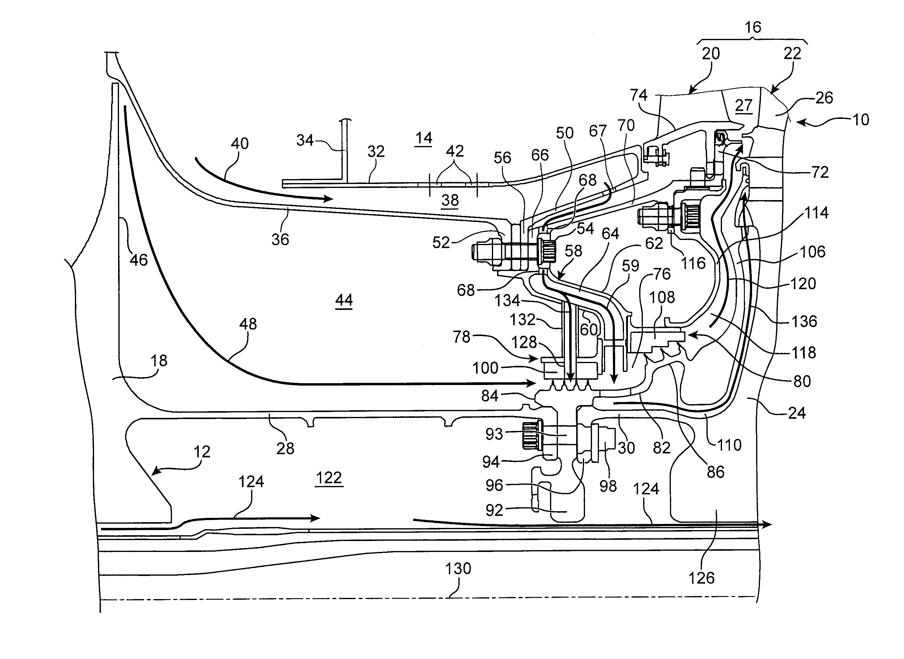
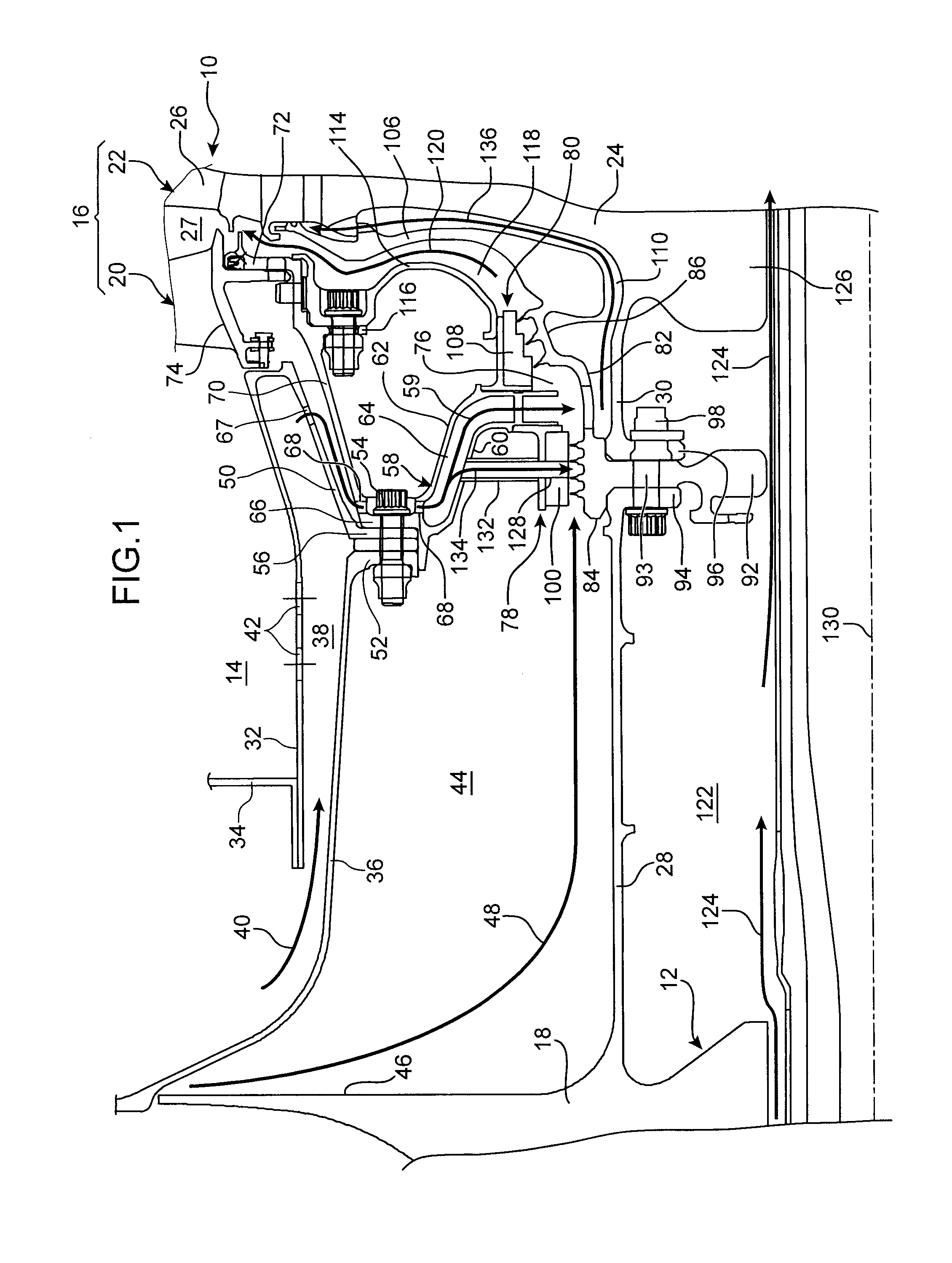
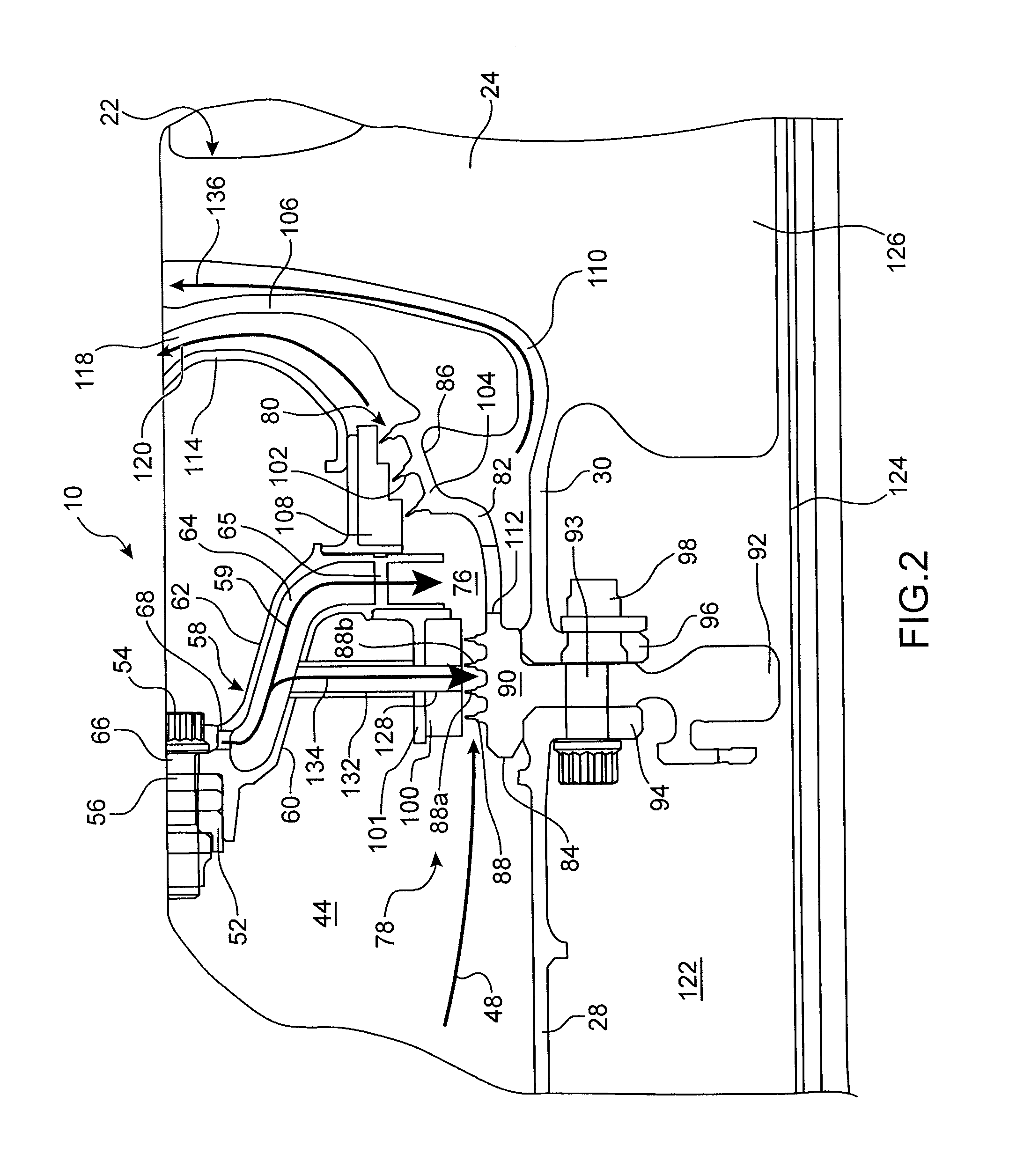
[0047]FIGS. 1 to 3 show part of a turbine engine 10, such as in particular an airplane turbofan or turboprop, according to a first embodiment of the invention.

[0048]As shown in FIG. 1, the turbine engine 10 comprises, from upstream to downstream, in the flow direction of the gases inside the turbine engine, a high-pressure compressor 12, an annular combustion chamber 14, and a high-pressure turbine 16, which are partially visible in FIG. 1.

[0049]The high-pressure compressor comprises, at its downstream end, a centrifugal impeller 18 intended to supply pressurized gas to the combustion chamber 14. This compressor can also comprise other rotary members such as vaned disks (not visible in FIG. 1) arranged upstream of the impeller 18.

[0050]The high-pressure turbine comprises an upstream distributor stage 20 and a downstream rotor stage 22. The latter comprises a rotatable disk 24 supporting vanes 26 that extend in the flow 27 of the combustion gases discharged by the combustion chamber ...


PUM


Abstract

A turbine engine including a channel for injecting a cooling air flow of a high-pressure turbine disk, opening into a cavity that is substantially isolated, upstream, from a cavity in which an air flow sampled at the output of a high-pressure compressor circulates, by a first labyrinth seal, and downstream, from a cavity communicating with the primary flow of the turbine engine, by a second labyrinth seal. The turbine engine includes channels communicating with the injection channel and opening through a static part of the first labyrinth seal between two lips of that seal, so as to allow an air flow coming from the injection channel to be injected between the lips.

Description

TECHNICAL FIELD[0001]The present invention relates to the field of twin-shaft turbine engines, and more particularly relates to the ventilation and cooling of components of the high-pressure compressor and the high-pressure turbine of those turbine engines.[0002]The invention more specifically relates to the adjustment of the flow rate of a cooling air flow sampled at the output of a high-pressure compressor in turbine engines.BACKGROUND OF THE INVENTION[0003]Twin-shaft turbine engines comprise a high-pressure turbine arranged at the output of a combustion chamber to remove energy from a primary gas flow discharged by said combustion chamber and drive a high-pressure compressor positioned upstream of the combustion chamber and supplying said chamber with pressurized air. These turbine engines also comprise a low-pressure turbine arranged downstream of the high-pressure turbine to remove excess energy from the primary gas flow and rotate a low-pressure compressor arranged upstream of...

Claims


Application Information

Patent Timeline
Patent Type & Authority Patents(United States)
IPC IPC(8): F02C7/12
CPCF01D5/082F01D25/12Y02T50/676Y02T50/60
Inventor GARIN, FABRICE MARCEL NOELJUDET, MAURICE GUYPASQUIS, PATRICK CLAUDESCHWEBLEN, WILFRIED LIONEL
Owner SN DETUDE & DE CONSTR DE MOTEURS DAVIATION S N E C M A
Learn More