Fluorescence microscope in a microwave cavity

a fluorescence microscope and microwave cavity technology, applied in the field of optical imaging system, can solve the problems of insufficient structure visibility or measurement ability of the copty system, and achieve the effect of sufficient resolution and increased chemical reaction tim

Active Publication Date: 2013-03-26
UNIV OF MARYLAND BALTIMORE COUNTY
View PDF18 Cites 14 Cited by
  • Summary
  • Abstract
  • Description
  • Claims
  • Application Information

AI Technical Summary

Benefits of technology

[0008]The present invention relates to an optical imaging system that provides for increases in chemical reaction times and the ability to monitor the reactions in real time with sufficient resolution to view the location of intracellular components labeled with luminescent molecules, as well as, interaction between multiple biomolecules and responses to localized environmental variables in living cells and tissues.
[0023]The sample plate may comprise at least one layer of metallic material deposited on the sample plate surface including silver, gold, copper, zinc, aluminum, or platinum wherein the metallic material is formed into a patterned shape. Preferably, the patterned shape includes geometric shapes having at least one apex, such as, a triangle, square, rectangle, trapezoid, polygon, parabola, elliptical, a sector of a circle, oblong and / or combinations thereof, wherein the numerous apexes are adjacent to each other, thereby creating a reactive zone therebetween. The reactive zone therebetween may further be prepared for placement of the immobilized capture molecule complementary to a detector molecule, chemicals for reacting with other chemicals, or biomolecules for reacting with other biomolecules. The reactive zone may have a diameter or distance between the adjacent and / or opposing apexes ranging from about 0.01 mm to 5 mm, and more preferably from about 2 mm to 3 mm. Further, the reactive zone can be positioned on assay system with multiple wells wherein the reactive zone is within the wells and exposure to microwave energy enhances the reactions therein.
[0024]The sample plate may be fabricated of a polymeric material, glass, paper, nitrocellulose, combinations thereof or any material that provides sufficient stability for placement of the metallic material.
[0025]The apex area / reactive zone is exposed to microwave energy in an amount to increase the reaction rate in biological interactions, to increase intensity of emissions from the chemiluminescence reaction, fluorescence, phosphorescence or luminescence tags in sensing technologies; to enhance electric fields by focusing electromagnetic fields in the reactive zone and / or to increase Brownian motion in molecules contained within the reactive zone.
[0038]The use of low power microwave energy directed at the sample that is positioned in a reactive zone formed by adjacent metallic patterns increases the speed of chemical reactions occurring within the sample.

Problems solved by technology

However, heretofore, the systems available could only look at the conditions before the reactions and then take another look after completion of the reactions [15, 20-22].
However, the system used by Copty did not provide sufficient visibility of structures or the ability to measure physiological and biochemical event in living cells.

Method used


Image

  • Fluorescence microscope in a microwave cavity
  • Fluorescence microscope in a microwave cavity
  • Fluorescence microscope in a microwave cavity

Examples


examples

[0077]Methods and Materials

[0078]Premium quality APS-coated glass slides (75×25 mm) were obtained from Sigma-Aldrich. CoverWell imaging chamber gaskets with adhesive (2.5 mm diameter, 2 mm deep and 5 mm diameter, 2 mm deep for temperature measurements) were obtained from Molecular Probes (Eugene, Oreg.). Ru(by)2Cl2 salt was obtained from Sigma-Aldrich. Commercially available chemiluminescence materials were purchased from Unique Industries, Inc.

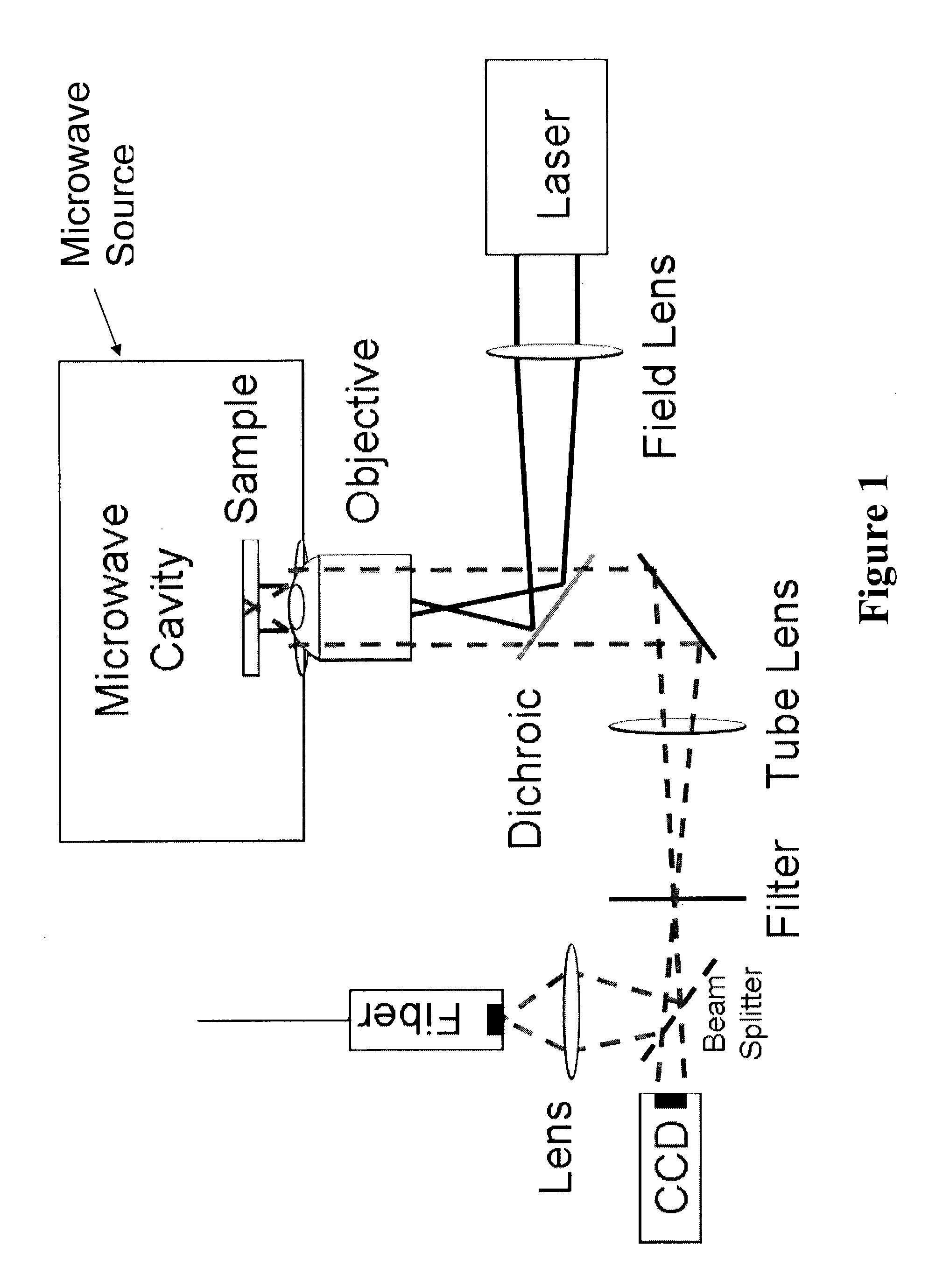
[0079]Optical Set-Up of Wide Field Microscope in Microwave Cavity

[0080]At the base of a microwave cavity (0.7 cu ft, GE Compact Microwave Model: JES735BF, max power 700 W), a 1 inch hole was drilled and subsequent exposed metal surfaces were covered with white enamel paint to prevent sparking and arcing. Using a beam expander the spot size of a 473 nm laser source was expanded to approximately 1 inch and focused to a point with a 175 mm lens at the back aperture of the objective. The incident excitation beam was reflected with a dichroic mirr...


PUM

PropertyMeasurementUnit
distanceaaaaaaaaaa
distanceaaaaaaaaaa
diameteraaaaaaaaaa

Abstract

The present invention relates to an optical imaging system communicatively connected to a microwave energy producing source wherein the combination provides for increases in chemical reaction times and the ability to monitor the reactions in real time with sufficient resolution to view the location of intracellular components labeled with luminescent molecules as well as interaction with other biomolecules and responses to localized environmental variables in living cells and tissues during the application of a microwave field.

Description

CROSS-REFERENCE TO RELATED APPLICATIONS[0001]This application is filed under the provisions of 35 U.S.C. §371 and claims the priority of International Patent Application No. PCT / US2008 / 065801 filed on Jun. 4, 2008, which in turn claims priority of U.S. Provisional Application No. 60 / 932,620 filed on Jun. 4, 2007, the contents of which are incorporated by reference herein for all purposes.BACKGROUND OF THE INVENTION[0002]1. Technical Field[0003]The present invention relates to an optical imaging system, and more particularly to the use of electromagnetic energy in the microwave or radiofrequency range in combination with an optical imaging device for imaging real time luminescent reactions.[0004]2. Related Art[0005]Optical microscopy is a well-established technique that has wide ranging applications for imaging molecular dynamics of biological systems. Typically, these applications rely on external temperature controllers to maintain or change reactions rates of these biological syst...

Claims


Application Information

Patent Timeline
Patent Type & Authority Patents(United States)
IPC IPC(8): C12Q1/68
CPCG01N21/6458G02B21/0004G01N21/6486G02B21/16G01N2021/6469Y10T436/143333Y10T436/201666
Inventor GEDDES, CHRIS D.PREVITE, MICHAEL J. R.
Owner UNIV OF MARYLAND BALTIMORE COUNTY
Why Eureka
Try Eureka