Waste gas recovery system device of noise elimination and air cooling static catalytic cracker of internal-combustion engine

A technology for exhaust gas recovery and system installation, which is used in exhaust installations, mufflers, internal combustion piston engines, etc.

Inactive Publication Date: 2010-03-03
上海徕普太阳能科技有限责任公司
View PDF0 Cites 15 Cited by
  • Summary
  • Abstract
  • Description
  • Claims
  • Application Information

AI Technical Summary

Problems solved by technology

[0007] In the development of automobile engines, due to the needs of environmental protection and sustainable social development, some non-power economic issues, such as the prevention and reduction of harmful emissions from automobile engines, will become a priority to be solved in a stage

Method used


Image

  • Waste gas recovery system device of noise elimination and air cooling static catalytic cracker of internal-combustion engine
  • Waste gas recovery system device of noise elimination and air cooling static catalytic cracker of internal-combustion engine
  • Waste gas recovery system device of noise elimination and air cooling static catalytic cracker of internal-combustion engine

Examples


Embodiment 1

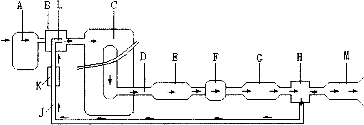
[0134] exist figure 2 Middle: (A) Air filter, (B) Exhaust gas recycling device, (L) Exhaust gas recycling nozzle, (J) Exhaust gas recycling connecting pipe, (C) Engine exhaust system, (D) Exhaust pipe, (E) Air-cooled static muffler, (F) Ozone generator, (G) Air-cooled static NO X Catalyst, (H) exhaust splitter, (M) air-cooled NO X Catalytic converter, (K) semiconductor refrigerator.

[0135] In the figure: (A) air filter is connected to (B) exhaust gas recycler, (C) engine exhaust system, (D) exhaust pipe, (E) air-cooled static muffler, (F) ozone Generator, (G) air-cooled static NO X Catalyst, (H) exhaust splitter, (M) air-cooled NO X Catalytic converter, (K) semiconductor refrigerator; exhaust gas returns to (B) exhaust gas recycling nozzle through (H) exhaust splitter (J) tail gas recycling connecting pipe in sequence ( C) Engine intake system.

Embodiment 2

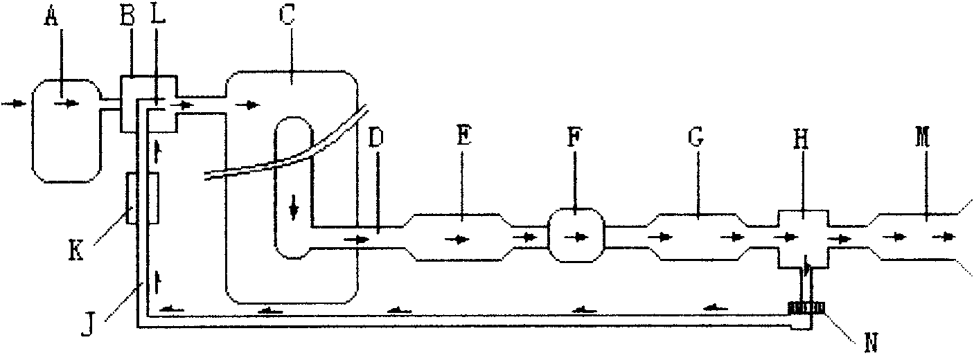
[0137] exist image 3 Middle: (A) Air filter, (B) Exhaust gas recycling device, (L) Exhaust gas recycling nozzle, (J) Exhaust gas recycling connecting pipe, (C) Engine exhaust system, (D) Exhaust pipe, (E) Air-cooled static muffler, (F) Ozone generator, (G) Air-cooled static NO X The catalytic converter is divided into two paths through the (H) exhaust splitter; the exhaust gas from one path is returned to the (L) in the (B) exhaust gas recycler through the (K) semiconductor refrigerator connected to the (J) exhaust gas recycling connecting pipe in sequence. Exhaust gas recovery nozzle enters (C) engine intake system; the other path passes through (H) exhaust splitter and connects to (M) air-cooled NO X Emissions after the catalytic converter.

[0138] In the figure: (A) air filter is connected to (B) exhaust gas recycler, (C) engine exhaust system, (D) exhaust pipe, (E) air-cooled static muffler, (F) ozone Generator, (G) air-cooled static NO X The catalytic converter is d...

Embodiment 3

[0140] exist Figure 4 Middle: (A) Air filter, (B) Exhaust gas recycling device, (L) Exhaust gas recycling nozzle, (J) Exhaust gas recycling connecting pipe, (C) Engine exhaust system, (D) Exhaust pipe, (E) Air-cooled static muffler, (F) Ozone generator, (Q) Air-cooled particulate filter, (H) Exhaust splitter, (N) Axial fan, (R) Air-cooled static hybrid catalyst.

[0141] In the figure: (A) air filter is connected to (B) exhaust gas recycler, (C) engine exhaust system, (D) exhaust pipe, (E) air-cooled static muffler, (F) ozone Generator, (Q) air-cooled particle trap is divided into two paths through (H) exhaust splitter; return exhaust is pumped by (N) axial flow fan to (J) exhaust gas recycling connecting pipe and returned to (B) ) The (L) exhaust gas recycling nozzle in the exhaust gas recycler enters (C) the engine intake system; the exhaust gas is discharged after being connected to (R) the air-cooled static hybrid catalytic converter through the (H) exhaust splitter.


PUM


Abstract

The invention relates to a waste gas recovery system device of a noise elimination and air cooling static catalytic cracker of an internal-combustion engine, comprising a tail gas recycling device, atail gas recycling nozzle, a tail gas recycling connecting pipe, an engine exhaust system, an exhaust pipe, an air cooling static noise eliminator, an ozone generator, an air cooling static NOX catalyst, an exhaust flow divider, an air cooling NOX catalyst, a semiconductor refrigerator, an axial flow fan, an air cooling particle catcher and an air cooling static mixing catalyst. The waste gas recovery system device is connected with an air supplying system and an oil line system so as to form new external three systems. The invention is suitable for a plane, a steamship, a diesel engine generating set, an internal-combustion locomotive, a motorcycle, a gasoline car, a diesel car, an oil drilling diesel machine, an industrial boiler, a domestic gas cooker, and the like, has simple and convenient installation, i.e. an original system of the internal-combustion engine is taken down and replace with the new system, can save the oil by 15-30 percent without exhaust pollution, prolongs the service life of the internal-combustion engine, is a major energy-saving brainstorm project during the Eleventh Five-Year Plan and is the major breakthrough of the waste gas recovery system--the reformation of the external three-system of an engine in 21 century.

Description

Technical field: [0001] Internal combustion engine (automobile engine) external exhaust and noise reduction system (hereinafter referred to as: external three systems) Background technique: [0002] Today in the 21st century, the depletion of non-renewable resources, the shortage of energy, and the pollution of the environment, doomed the development of new technologies and new energy throughout the entire era. Energy shortage and air pollution have become two major problems in today's world. The changes of history, the transformation of time and space, and the development of each era have their own witnesses - oil, steel, automobiles, electronics, IT industry... [0003] The current society is constantly progressing, environmental pollution is intensifying, energy demand is rising, and oil prices are soaring all the way, worrying all mankind! It is our desire to save fuel and protect the environment. Reducing air pollution emissions is the only way to protect our living e...

Claims


Application Information

Patent Timeline
Patent Type & Authority Applications(China)
IPC IPC(8): F02M25/07F01N3/28F01N3/021F01N7/08B01D53/94F02M26/51
CPCY02T10/121Y02T10/12
Inventor 陈绍勇丁朝霞
Owner 上海徕普太阳能科技有限责任公司
Why Eureka
Try Eureka