Capacitive coupling radio frequency normal pressure plasma torch for machining ultra-smooth surface

An ultra-smooth surface, atmospheric pressure plasma technology, applied in the field of plasma polishing equipment, can solve the problems of difficult surface cleaning, easy corrosion of the inner torch, low efficiency, etc.

Inactive Publication Date: 2006-11-22
HARBIN INST OF TECH
View PDF0 Cites 15 Cited by
  • Summary
  • Abstract
  • Description
  • Claims
  • Application Information

AI Technical Summary

Problems solved by technology

[0003] The purpose of the present invention is to solve the problems of low efficiency, easy surface and sub-surface damage, difficult surface cleaning and large-scale Problems existing in the processing of light mirrors and plasma torches have the problems of easy corrosion of the inner torch tube, high cost, and poor system maintainability. A capacitively coupled radio frequency atmospheric pressure plasma for ultra-smooth surface processing is provided. body torch

Method used


Image

  • Capacitive coupling radio frequency normal pressure plasma torch for machining ultra-smooth surface
  • Capacitive coupling radio frequency normal pressure plasma torch for machining ultra-smooth surface
  • Capacitive coupling radio frequency normal pressure plasma torch for machining ultra-smooth surface

Examples


specific Embodiment approach 1

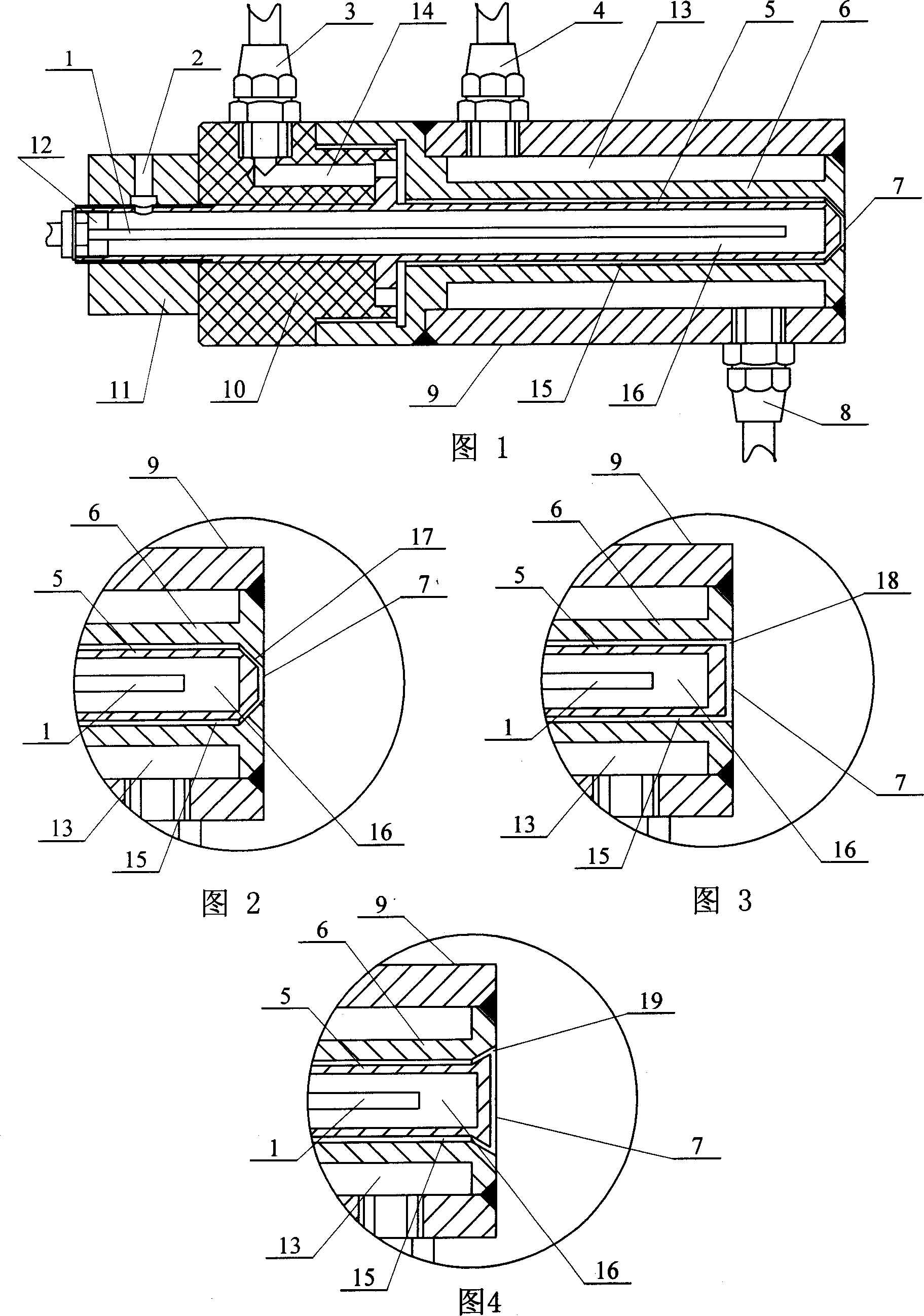
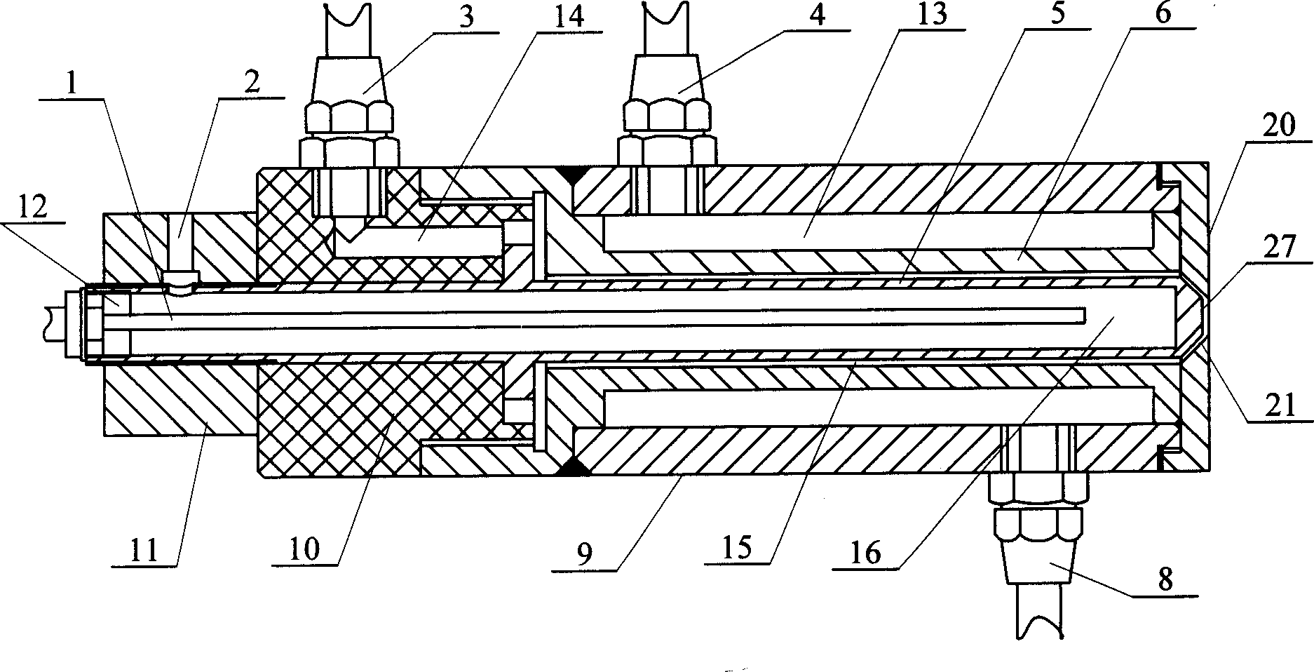
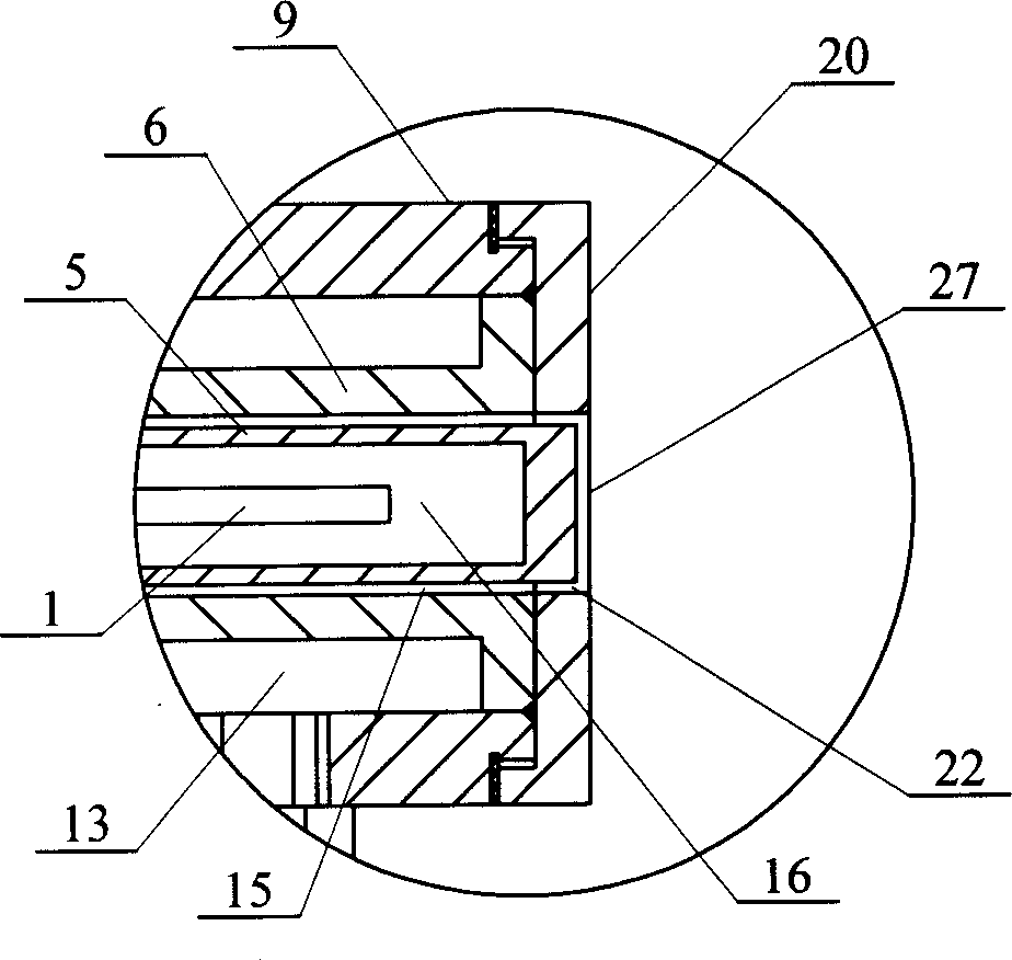
[0005] Specific embodiment one: (see Fig. 1, Fig. 2) this embodiment is composed of anode water-cooling conduit 1, air intake joint 3, cathode water-cooling joint one 4, anode 5, cathode 6, cathode water-cooling joint two 8, jacket 9, ceramic nut 10. The connecting body 11 and the sealing seat 12 are composed, the cathode 6 is fixedly connected with the jacket 9, a water-cooled annular space 13 is formed between the outer wall of the cathode 6 and the inner wall of the jacket 9, and the cathode water-cooling joint 4 is fixed on the outer wall of one side of the jacket 9 And communicated with the water-cooled annular space 13, the cathode water-cooled connector 2 8 is fixed on the outer wall of the other side of the jacket 9 and communicated with the water-cooled annular space 13, the right end of the ceramic nut 10 is fixedly connected with the left end of the cathode 6, and the connecting body 11 The right end is fixedly connected with the left end of the ceramic nut 10, the l...

specific Embodiment approach 2

[0006] Specific embodiment two: (referring to Fig. 1, Fig. 2) the outlet 7 of the cathode 6 of the present embodiment is a small truncated cone shape 17 with a large inner mouth and a small outer mouth, and the right end of the anode 5 corresponds to the truncated cone shape 17 of the outlet 7 of the cathode 6. Other compositions and connections are the same as in the first embodiment.

specific Embodiment approach 3

[0007]Specific Embodiment Three: (See FIG. 3 ) The outlet 7 of the cathode 6 in this embodiment is straight-shaped 18 , and the right end of the anode 5 corresponds to the straight-shaped 18 of the outlet 7 of the cathode 6 . Other composition and connection relationship with

[0008] The specific embodiment one is the same.


PUM

PropertyMeasurementUnit
thicknessaaaaaaaaaa

Abstract

The invention relates to a capacitor coupling radio normal-voltage plasma saw used in ultra-smooth surface machining, especially providing a plasma polishing device. Wherein, the invention is purposed to solve the problems of general mechanical polishing method, as low efficiency, high cost and worse maintenance, etc. It forms a water cold annular space (13) between the outer wall of cathode (6) and the inner wall of outer sheath (9), and arranges the anode water cold tube (1) inside the chamber (16) of anode (5). The invention can avoid vacuum room, while its efficiency is 10 times of traditional polish method, and it will not hurt the surface. The invention can realize high-efficiency high-quality treatment on the optical element.

Description

technical field [0001] The invention relates to an atmospheric pressure plasma polishing equipment. Background technique [0002] The development of modern short-wave optics, strong light optics, electronics and thin film science has very strict requirements on the surface, and its obvious characteristic is that the surface roughness is less than 1nm Ra. When this type of surface is used as an optical element, in order to obtain the highest reflectivity, special emphasis is placed on low surface scattering characteristics or extremely low roughness values; when used as a functional element, because most of them are crystal materials, more attention is paid to the surface roughness. Lattice integrity of the surface. We collectively refer to these two types of surfaces as ultra smooth surfaces. Ultra-smooth optical parts are mostly processed by diamond ultra-precision cutting or various traditional grinding and polishing processes. Ultra-precision diamond cutting itself can...

Claims


Application Information

Patent Timeline
Patent Type & Authority Applications(China)
IPC IPC(8): B24B1/00
Inventor 王波张巨帆张龙江王浪平董申
Owner HARBIN INST OF TECH
Why Eureka
Try Eureka