Thermally protected light emitting diode module

a technology of light-emitting diodes and modules, which is applied in the direction of fixed installation, lighting and heating equipment, lighting support devices, etc., can solve the problems of complicated disposal of cfls, environmental concerns, and leds that cannot fit in existing incandescent lamp sockets, and achieve the effect of shortening the circui

Active Publication Date: 2013-03-26
SIGNIFY HLDG BV
View PDF2 Cites 67 Cited by
  • Summary
  • Abstract
  • Description
  • Claims
  • Application Information

AI Technical Summary

Benefits of technology

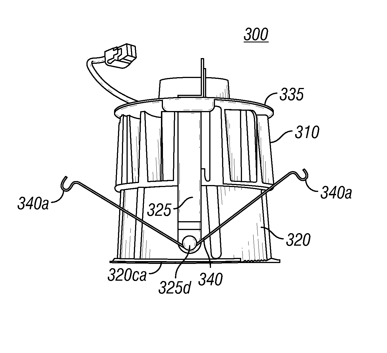
[0008]The invention provides a recessed light fixture with an LED light source. The light fixture includes a housing or “can” within which an LED module is mounted. The LED module includes a single LED package that generates all or substantially all the light emitted by the recessed light fixture. For example, the LED package can include one or more LEDs mounted to a common substrate. Each LED is an LED die or LED element that is configured to be coupled to the substrate. The LEDs can be arranged in any of a number of different configurations. For example, the LEDs can be arranged in a round-shaped area having a diameter of less than two inches or a rectangular-shaped area having a length of less than two inches and a width of less than two inches.
[0009]The LED package can be thermally coupled to a heat sink configured to transfer heat from the LEDs. The heat sink can have any of a number of different configurations. For example, the heat sink can include a core member extending away from the LED package and fins extending from the core member. Each fin can include a curved, radial portion and / or a straight portion. For example, each fin can include a radial portion that extends from the core member, and a straight portion that further extends out from the radial portion. In this configuration, heat from the LEDs can be transferred along a path from the LEDs to the core member, from the core member to the radial portions of the fins, from the radial portions of the fins to their corresponding straight portions, and from the corresponding straight portions to a surrounding environment. Heat also can be transferred by convection directly from the core member and / or the fins to one or more gaps between the fins. The LED package can be coupled directly to the core member or to another member disposed between the LED package and the core member.
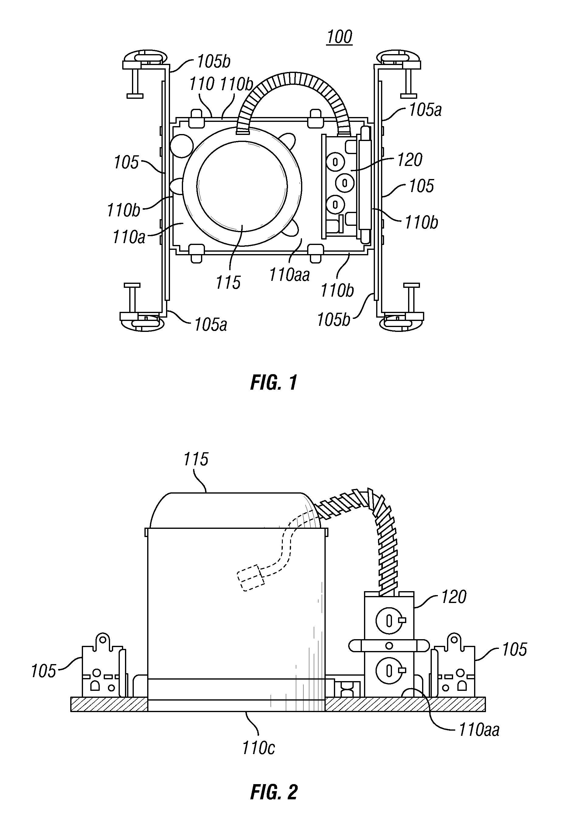
[0010]The LED module can be used in both new construction and retrofit applications. The retrofit applications can include placing the LED module in an existing LED or non-LED fixture. To accommodate installation in a non-LED fixture, the LED module can further include a member comprising a profile that substantially corresponds to an interior profile of a can of the non-LED fixture such that the member creates a junction box between the member and a top of the can when the LED module is mounted in the can. To install the LED module, a person can electrically couple an Edison base adapter to both the existing, non-LED fixture and the LED module. For example, a person can cut at least one wire to remove an Edison base from the existing fixture, cut at least one other wire to remove an Edison screw-in plug from the Edison base adapter, and connect together the cut wires to electrically couple the Edison base adapter and the existing fixture. Alternatively, a person can release a socket from the existing fixture and screw the Edison base adapter into the socket to electrically couple the Edison base adapter and the existing fixture. The junction box can house the Edison base adapter and at least a portion of the wires coupled thereto.
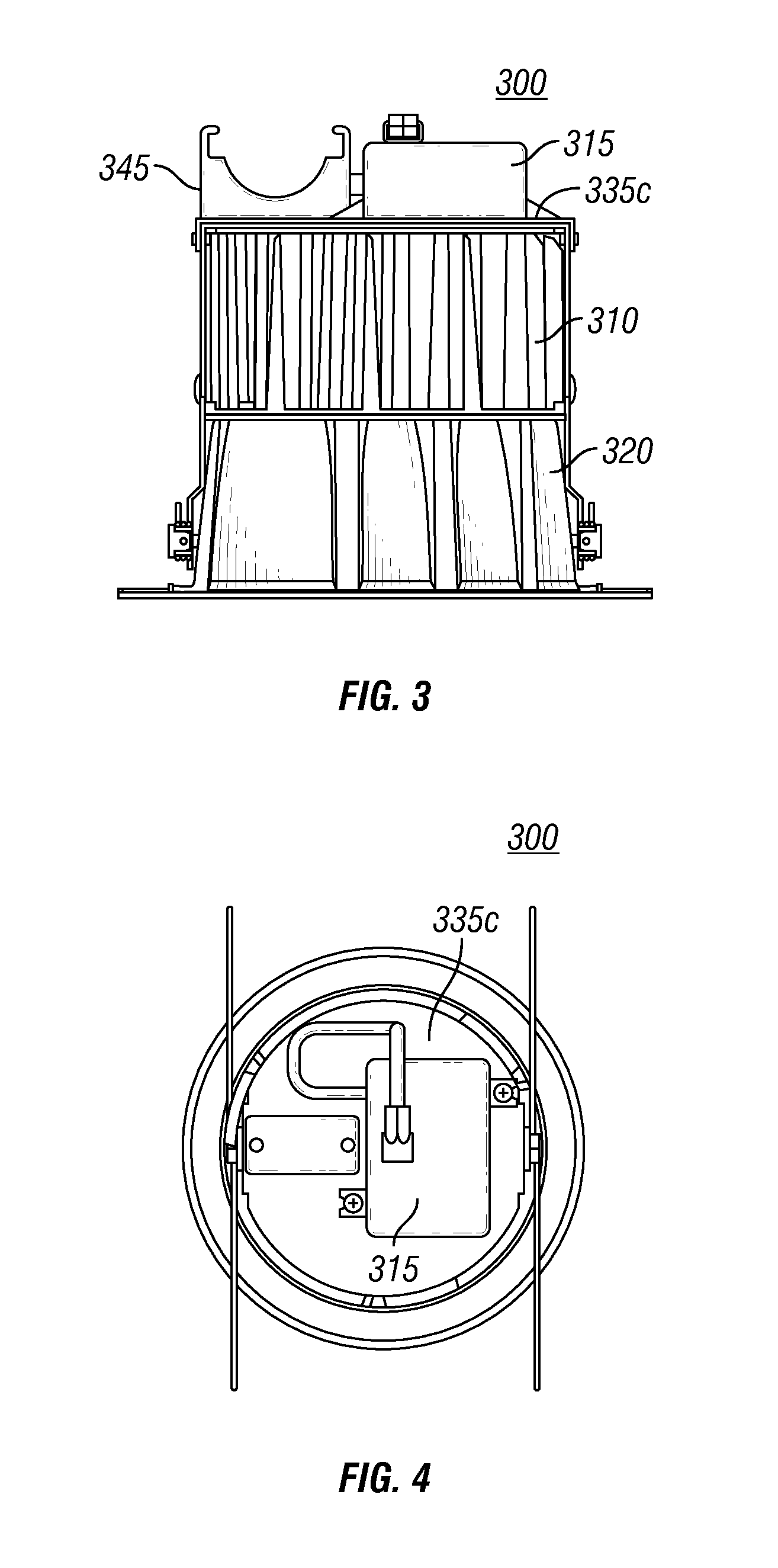
[0011]A thermally protected LED module can be used in new installation and retrofit installation applications. The thermally protected LED module can include a thermal protector, such as a thermal switch, electrically coupled to an LED driver and a power source to create a circuit from the power source to the driver. The thermal protector can be mounted to a mounting bracket that the driver is mounted to, or to the driver itself. Alternatively, the thermal protector may be “floating” and measure the temperature in an area proximate to the driver and / or the mounting bracket. The thermal protector can include a thermal rating that, when exceeded, opens the circuit and removes current flowing from the power source to the driver. For example, the thermal protector can activate when the temperature being monitored by the thermal protector is at least 10 degrees Celsius below a maximum operating temperature of the driver. In some instances, the thermal protector can be activated when the temperature of the mounting bracket reaches 80 degrees Celsius. An insulating sleeve, such as a plastic cover, can enclose the thermal protector and prevent the thermal protector from contacting other metal parts and shorting the circuit. The thermally protected LED module can also include a thermal protector cover, or clip, having a cavity in which the thermal protector is positioned and secured. In some instances, the thermal protector cover includes a tab that applies a force on the thermal protector sufficient to maintain physical contact between the thermal protector and the driver or mounting bracket surface.

Problems solved by technology

However, CFLs include mercury, which complicates disposal of the CFLs and raises environmental concerns.
However, LEDs do not fit in existing incandescent lamp sockets and generally require complex electrical and thermal management systems.
Therefore, traditional recessed light fixtures have not used LED light sources.
However, the insulation protectors are not typically universal voltage, for example, they may not able to receive two different line voltages, and therefore may require two separate housings for various voltage applications.
However, thermal protectors on the housing of the light fixtures have not been successful to date in thermal protection, since the LED modules may not radiate enough heat to the housing to trip a housing mounted thermal protector, even if a component of the LED module, such as the driver, exceeds its thermal limit.

Method used


Image

  • Thermally protected light emitting diode module
  • Thermally protected light emitting diode module
  • Thermally protected light emitting diode module

Examples


example

[0088]LED modules, as described with respect to FIGS. 21-22, having an automatic reset thermal switch positioned on the mounting bracket were tested to determine whether the LED modules can operate safely and effectively using various trims under varying conditions. The trim is the visible portion of the light fixture, and is the insert that is seen when looking up into the fixture, and also includes the thin lining around the edge of the light fixture. The thermal switches used in the tests are commercially available from Sensata Technologies, Inc. All of the tests utilized a thermal switch with a catalog number of 7AM023A5, with a thermal rating, or designated threshold temperature, of 80 degrees Celsius, except in test #2 in Table 1 below. In that test, a thermal switch having a catalog number of 7AM038A5, with a thermal rating of 155 degrees Celsius was used. LED modules having 25 watt (W) LEDs were supplied with a line voltage of about 120 volts (V). Some of the LED modules wer...


PUM


Abstract

A recessed light fixture includes a thermally protected light emitting diode (“LED”) module. The thermally protected LED module includes a thermal protector positioned in series between a source of electrical power and an LED driver and is configured to open a circuit to prevent power from being supplied by the power source to the LED driver for an LED package when a thermal rating or activation temperature of the thermal protector is exceeded. For example, the maximum operating temperature of the LED driver may be 90 degrees Celsius, and the thermal rating of the thermal protector may be 80 degrees Celsius, and when the temperature of the driver or a mounting bracket upon which the driver is mounted reaches 80 degrees Celsius, the thermal protector opens a circuit and removes current flow from the power source to the driver, thereby removing power to the LED package.

Description

CROSS-REFERENCE TO RELATED APPLICATIONS[0001]This application is related to U.S. patent application Ser. No. 12 / 235,116, titled “Light Emitting Diode Recessed Light Fixture,” filed Sep. 22, 2008, and U.S. patent application Ser. No. 12 / 235,146, titled “Thermal Management for Light Emitting Diode Fixture,” filed Sep. 22, 2008. The complete disclosure of each of the foregoing related applications is hereby fully incorporated herein by reference.TECHNICAL FIELD[0002]The invention relates generally to thermal protection of luminaires, and more particularly, to thermal protection of a light emitting diode module of a downlight can fixture for a recessed luminaire.BACKGROUND OF THE INVENTION[0003]A luminaire is a system for producing, controlling, and / or distributing light for illumination. For example, a luminaire can include a system that outputs or distributes light into an environment, thereby allowing certain items in that environment to be visible. Luminaires are often referred to a...

Claims


Application Information

Patent Timeline
Patent Type & Authority Patents(United States)
IPC IPC(8): H02H5/00
CPCF21V21/04F21S8/026F21V23/008H05B33/08F21V25/10F21Y2101/02F21Y2115/10H05B45/357H05B45/3574H05B45/56Y02B20/30
Inventor GREEN, RUSSELL BRYANTCLARKE, TERENCE JAMAL
Owner SIGNIFY HLDG BV
Why Eureka
Try Eureka