Auto-exposure method using continuous video frames under controlled illumination

a continuous video and illumination technology, applied in the field of digital image capture and processing systems, can solve the problems of waste of at least one video frame, time-consuming auto-exposure method, and subsequent frame in the video

Active Publication Date: 2013-04-02
METROLOGIC INSTR
View PDF43 Cites 808 Cited by
  • Summary
  • Abstract
  • Description
  • Claims
  • Application Information

AI Technical Summary

Benefits of technology

[0008]Accordingly, a primary object of the present disclosure is to provide a novel digital image capture and processing system and method, which avoid the shortcomings and drawbacks of prior art methods and apparatus.
[0009]Another object is to provide a digital image capture and processing system having a digital image formation and detection subsystem, supporting a continuous video image capture mode, having a variable stroboscopically-pulsed illumination (i.e. strobe illumination) duration, synchronized with each image exposure period, so as to help provide an improved level of responsiveness while ensuring high-quality image capture performance.
[0011]Another object is to provide such a digital image capture and processing system, wherein the digital image formation and detection subsystem employs an optical band-pass filter designed to pass optical bandwidth of LED-based strobe illumination, during illumination transmission and collection operations, while blocking out optical components of ambient light residing outside the optical bandwidth of LED strobe illumination, thereby reducing the dynamic range of the image as well as improve the accuracy of exposure estimation based on previous images.

Problems solved by technology

Therefore, if the previous exposure time is incorrect, while the computer is still analyzing the first acquired image, subsequent frame in the video is wasted since it is taken with the same exposure time.
The resulting effect is a time-consuming auto-exposure method and at least one frame of the video is wasted.

Method used


Image

  • Auto-exposure method using continuous video frames under controlled illumination
  • Auto-exposure method using continuous video frames under controlled illumination
  • Auto-exposure method using continuous video frames under controlled illumination

Examples


Embodiment Construction

[0024]Referring to the figures in the accompanying Drawings, the illustrative embodiments of the digital imaging-based bar code symbol reading system will be described in great detail, wherein like elements will be indicated using like reference numerals.

[0025]In general, two illustrative embodiments of the digital-imaging based bar code symbol reading system are described hereinbelow. In each illustrative embodiment, an adaptive strobe illumination and exposure control process is supported, which helps provide an improved level of snappiness and / or responsiveness to system performance.

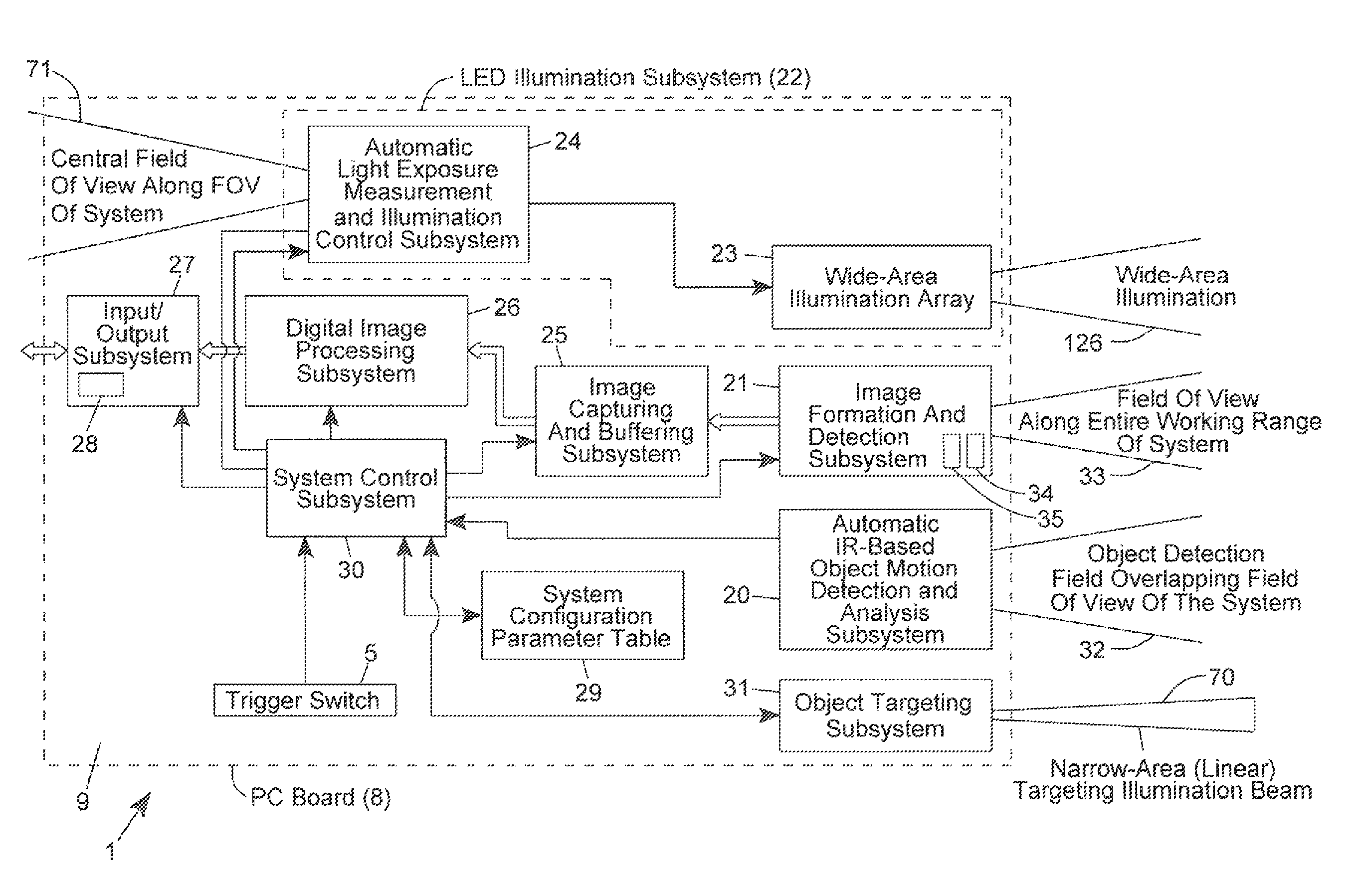
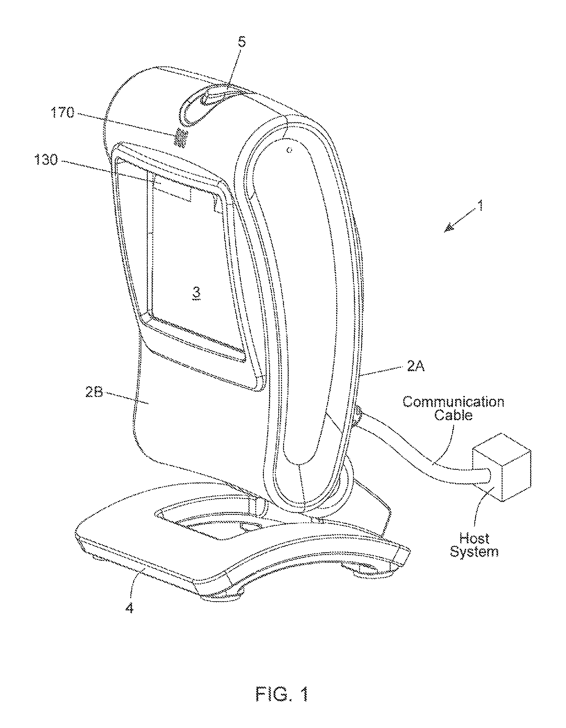
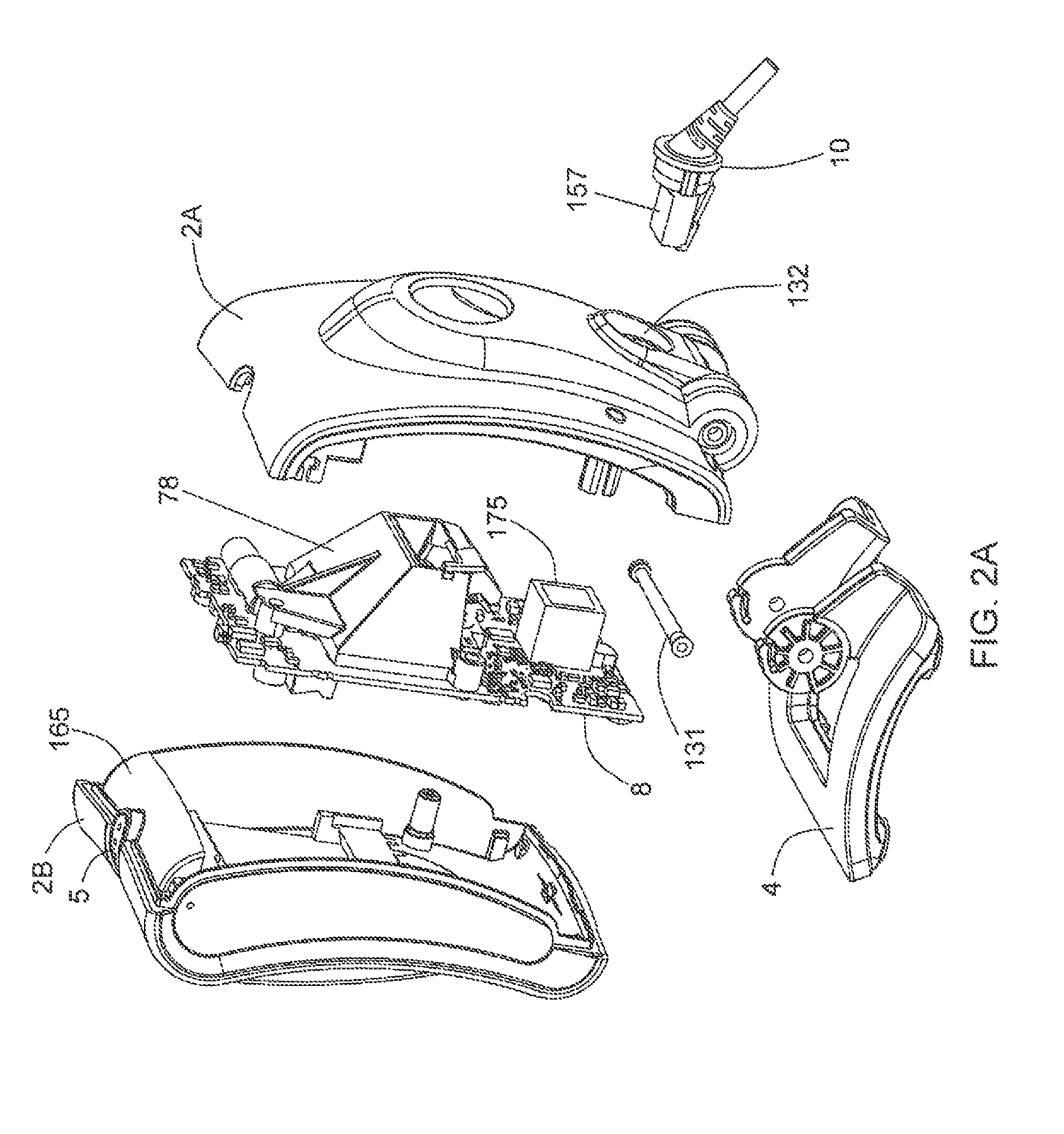
[0026]As shown in FIGS. 1, 2A and 2B, the digital-imaging based bar code symbol reading system of the illustrative embodiment 1 comprises: a hand-supportable housing 2 having (i) a front housing portion 2B with a window aperture 6 and an imaging window panel 3 installed therein; and (ii) a rear housing portion 2A. As shown, a single PC board based optical bench 8 (having optical subassemblies mounted ...


PUM


Abstract

An adaptive strobe illumination control process for use in a digital image capture and processing system. In general, the process involves: (i) illuminating an object in the field of view (FOV) with several different pulses of strobe (i.e. stroboscopic) illumination over a pair of consecutive video image frames; (ii) detecting digital images of the illuminated object over these consecutive image frames; and (iii) decode processing the digital images in an effort to read a code symbol graphically encoded therein. In a first illustrative embodiment, upon failure to read a code symbol graphically encoded in one of the first and second images, these digital images are analyzed in real-time, and based on the results of this real-time image analysis, the exposure time (i.e. photonic integration time interval) is automatically adjusted during subsequent image frames (i.e. image acquisition cycles) according to the principles of the present disclosure. In a second illustrative embodiment, upon failure to read a code symbol graphically encoded in one of the first and second images, these digital images are analyzed in real-time, and based on the results of this real-time image analysis, the energy level of the strobe illumination is automatically adjusted during subsequent image frames (i.e. image acquisition cycles) according to the principles of the present disclosure.

Description

BACKGROUND OF INVENTION[0001]1. Field of Disclosure[0002]The present disclosure relates to digital image capture and processing systems employing improved methods of automatic illumination control during a continuous video image capture mode of operation.[0003]2. Brief Description of the State of the Art[0004]Auto-exposure methods used in imaging devices typically involve the steps of (a) acquiring an image with a certain exposure time, (b) analyzing the acquired image and (c) determining if an exposure period needs to be set, and (d) repeating these steps until the image exposure quality meets a predetermined threshold. In the case of imaging barcode scanners, sometimes the imager is running in video mode.[0005]Therefore, if the previous exposure time is incorrect, while the computer is still analyzing the first acquired image, subsequent frame in the video is wasted since it is taken with the same exposure time. The resulting effect is a time-consuming auto-exposure method and at ...

Claims


Application Information

Patent Timeline
Patent Type & Authority Patents(United States)
IPC IPC(8): G06K7/10G06K9/24G08C21/00
CPCG06K7/10732G06K7/10752H04N5/2353F21Y2115/10H04N23/56H04N23/73F21V33/0052F21W2131/30
Inventor ZHU, XIAOXUNWANG, YNJIUN PAUL
Owner METROLOGIC INSTR
Why Eureka
Try Eureka