Light recycling directional control element and light emitting device using the same

a technology of directional control and light emitting device, applied in the field of optical elements, can solve the problems of limitations of traditional prismatic collimation film in their ability to highly collimate incident light, and achieve the effect of increasing spatial color or luminance uniformity

Active Publication Date: 2013-04-02
MASSACHUSETTS DEV FINANCE AGENCY
View PDF28 Cites 104 Cited by
  • Summary
  • Abstract
  • Description
  • Claims
  • Application Information

AI Technical Summary

Benefits of technology

[0004]In one embodiment of this invention, an optical element comprises a light recycling directional control element and provides increased spatial color or luminance uniformity, desired angular color uniformity, and customizable light re-direction properties. In one embodiment, the optical element comprises at least one light blocking region and a lenticular lens element. Further embodiments incorporate an anisotropic ligh

Problems solved by technology

Traditional prismatic collimation films have limitations

Method used


Image

  • Light recycling directional control element and light emitting device using the same
  • Light recycling directional control element and light emitting device using the same
  • Light recycling directional control element and light emitting device using the same

Examples


example 1

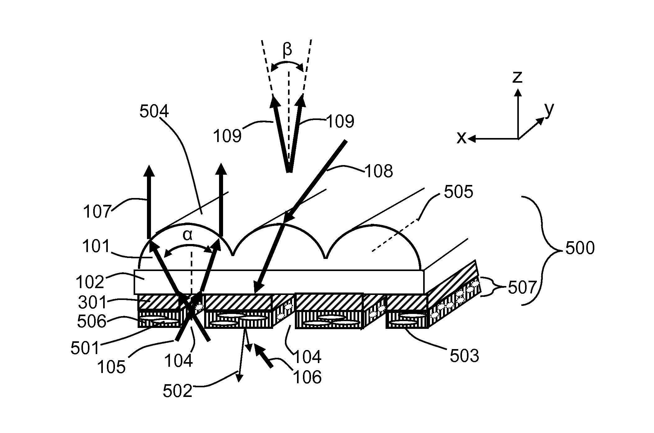
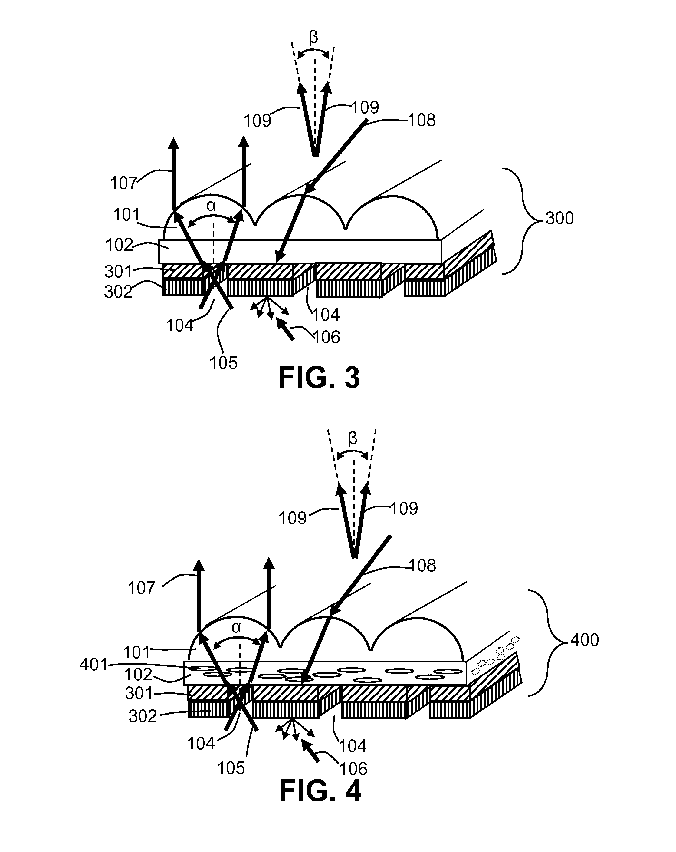
[0169]An optical element is made from a 187 micron lenticular lens array film printed on the flat side with linear array of white lines using a laser transfer process. The white lines were aligned substantially parallel to the lenticules and in the regions directly beneath the apex of the lenticules. The white lines are approximately 100 μm wide with a pitch of approximately 187 μm. The optical element is positioned above an edge-lit waveguide with light extraction features and a white PET-based reflector on the opposite side. The light output from the resulting light emitting device has far-field peak illuminance angles greater than 30 degrees from the normal.

example 2

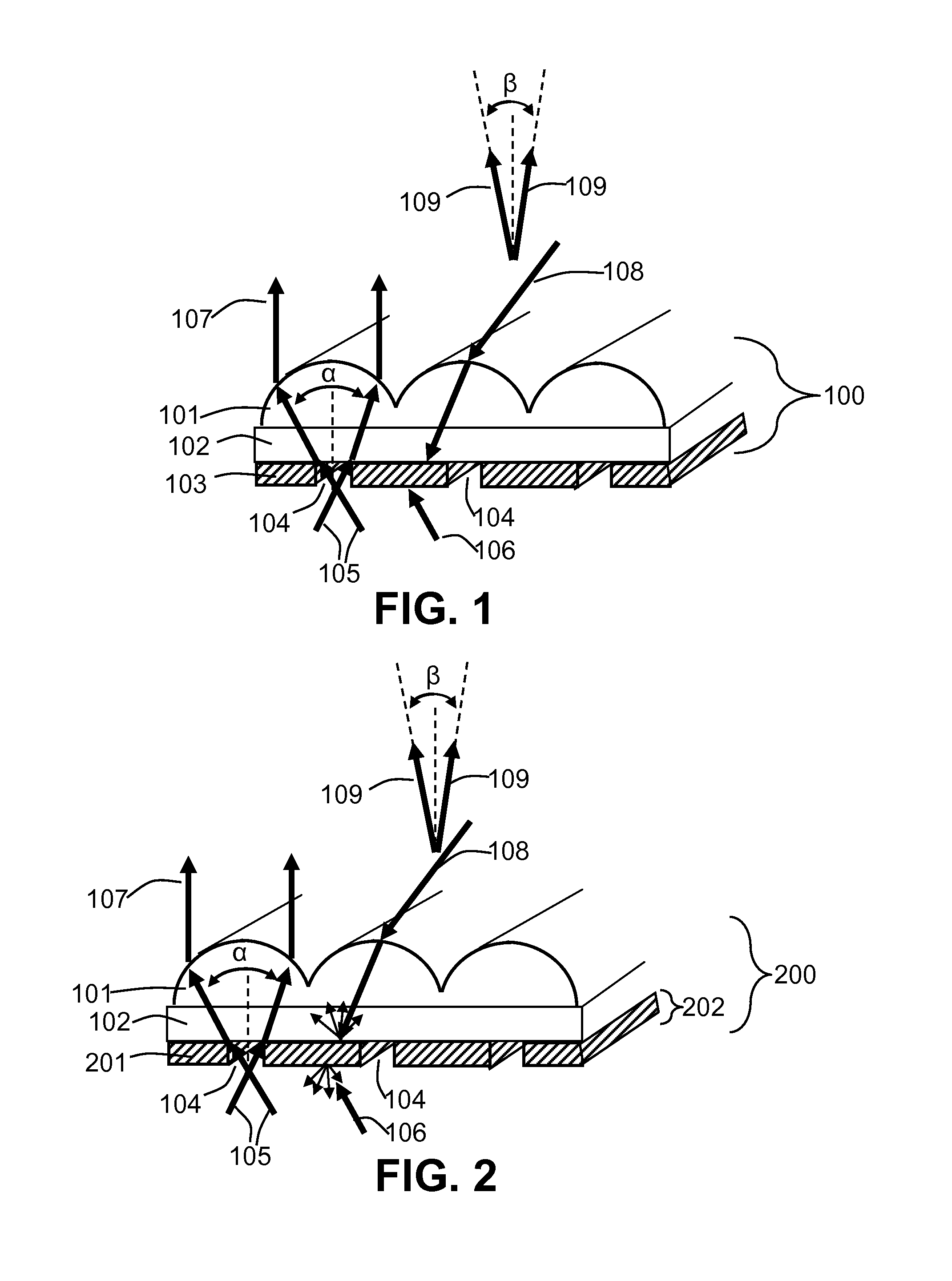
[0170]An optical element is made from a 187 micron lenticular lens array film laminated with Cromalin light sensitive film from DuPont Inc. Collimated UV light from a 1 kW Tamarack UV exposure system is directed to the lenticular film at angle of 15 degrees from the normal to the film such that the light passes through the lenticular elements and exposes the Cromalin light sensitive film. The protective cover is removed from the Cromalin and white titanium dioxide powder is then applied by soft brush to the cromalin film. The film is then blanket UV cured to fully cure the Cromalin. When the optical element is positioned on a diffuser sheet which is directly illuminated by LEDs with the light incident on the light reflecting surface, the far-field peak angle of illuminance is at 15 degrees and light is visible in the angular ranges corresponding to light passing through the white regions.

example 3

[0171]An optical element is made from a 187 micron lenticular lens array film laminated with Cromalin light sensitive film from DuPont Inc. Collimated UV light from a 1 kW Tamarack UV exposure system is directed to the lenticular film at angle of 15 degrees from the normal to the film such that the light passes through the lenticular elements and exposes the Cromalin light sensitive film. The protective cover is removed from the Cromalin and carbon black powder is then applied by soft brush to the Cromalin film. The film is then blanket UV cured to fully cure the Cromalin. A second layer of Cromalin film is laminated to the first Cromalin film. The optical element is then exposed similarly with collimated UV light directed at 15 degrees. The protective cover is removed from the Cromalin and white titanium dioxide powder is then applied by soft brush to the second layer of Cromalin film. The film is then blanket UV cured to fully cure the Cromalin. This resulted in an optical element...


PUM


Abstract

In one embodiment of this invention, an optical element comprises a light recycling directional control element and provides increased spatial color or luminance uniformity, desired angular color uniformity, and customizable light re-direction properties. In one embodiment, the optical element comprises at least one light blocking region and a lenticular lens element. Further embodiments incorporate an anisotropic light backscattering region within a light transmitting layer. The optical element may further comprise a light collimating element or an additional light lenticular lens element and light transmitting region that may be oriented parallel or perpendicular to the first lenticular lens element. Light emitting devices and displays incorporating the light recycling direction control element are further embodiments of this invention.

Description

RELATED APPLICATIONS[0001]This applications claims the benefit of U.S. Provisional Application No. 61 / 036,062, filed on Mar. 12, 2008, the entire contents are incorporated herein by reference.FIELD OF THE INVENTION[0002]This invention generally relates to optical elements for recycling and spatial and angular control of light and using these elements in a light emitting device such as a light fixture, backlight, display sign to control at least one of properties of light output profile, viewing angles, uniformity, form factor, and efficiency.BACKGROUND OF THE INVENTION[0003]Light collimating films can be used in backlights for displays or signs to collimate the light and increase uniformity through total internal reflections. Traditional prismatic collimation films have limitations on their ability to highly collimate the incident light. Current methods for improving the uniformity of light in a backlight often involve excess diffusion, light absorption and generally the thickness o...

Claims


Application Information

Patent Timeline
IPC IPC(8): F21V7/04
CPCG02F1/133526F21V7/04
Inventor COLEMAN, ZANE
Owner MASSACHUSETTS DEV FINANCE AGENCY
Why Eureka
Try Eureka