Display device with floating bar

a display device and floating bar technology, applied in static indicating devices, non-linear optics, instruments, etc., can solve the problems of image display errors, short circuits of floating bars with data lines, etc., and achieve the effect of preventing a delay of data signals

Active Publication Date: 2013-04-02
ZEON CORP +1
View PDF52 Cites 0 Cited by
  • Summary
  • Abstract
  • Description
  • Claims
  • Application Information

AI Technical Summary

Benefits of technology

[0012]An exemplary embodiment of the present invention has been made in an effort to provide a display device having the advantages of preventing a delay of a data signal.

Problems solved by technology

During or after the manufacturing of the display device, the floating bar may become short-circuited with the data line because of minute particles, etc.
This may cause a load at the data line so as to cause a delay therein, so there may be a problem in that images are not properly displayed.

Method used


Image

  • Display device with floating bar
  • Display device with floating bar
  • Display device with floating bar

Examples


Embodiment Construction

[0025]The present invention will be described more fully hereinafter with reference to the accompanying drawings, in which exemplary embodiments of the invention are shown.

[0026]First, a display device according to an exemplary embodiment of the present invention will be explained in detail with reference to FIG. 1 and FIG. 2, and the explanation will be given using the example of a liquid crystal display.

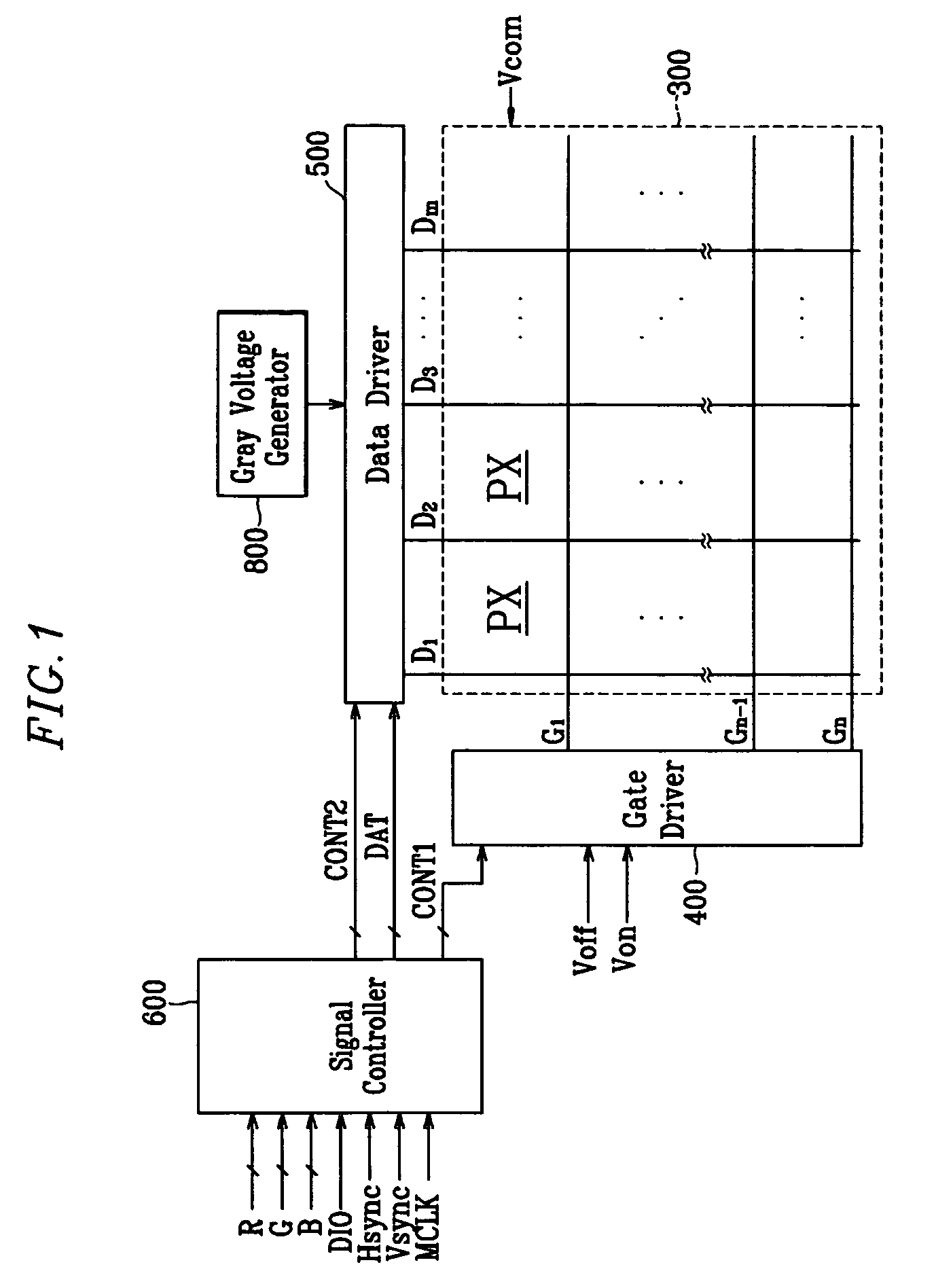
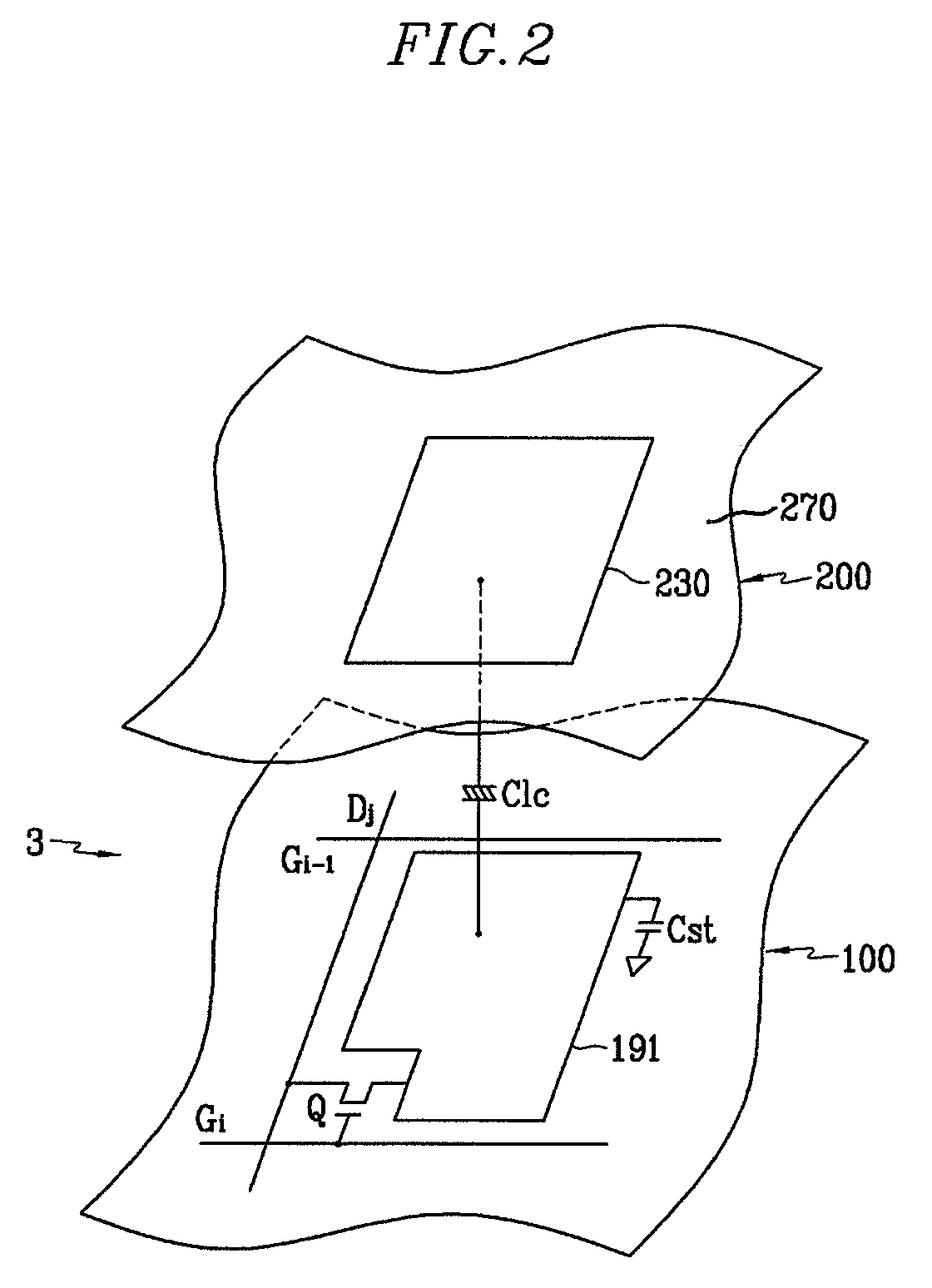
[0027]FIG. 1 is a block diagram of a liquid crystal display according to an exemplary embodiment of the present invention, and FIG. 2 is an equivalent circuit diagram of one pixel of a liquid crystal display according to an exemplary embodiment of the present invention.

[0028]As shown in FIG. 1, a liquid crystal display according to an exemplary embodiment of the present invention includes a liquid crystal panel assembly 300, a gate driver 400 and a data driver 500 connected to the liquid crystal panel assembly 300, a gray voltage generator 800 connected to the data driver 500, and ...


PUM


Abstract

A display device includes a plurality of pixels, a data line transmitting a data voltage to the pixels, and a floating bar crossing the data line and being divided into a plurality of pieces. By dividing the floating bar into a plurality of pieces, a delay of a data signal can be prevented so that excellent images can be displayed. Furthermore, by disposing a diode between the pieces of the floating bar, an effect of dispersing static electricity can be maximized.

Description

CROSS-REFERENCE TO RELATED APPLICATION[0001]This application claims priority to and the benefit of Korean Patent Application No. 10-2005-0108449 filed in the Korean Intellectual Property Office on Nov. 14, 2005, the entire contents of which are incorporated herein by reference.BACKGROUND OF THE INVENTION[0002](a) Technical Field[0003]The present disclosure relates to a display device, and more particularly to a structure of a floating bar of a display device.[0004](b) Discussion of the Related Art[0005]Recently, instead of heavy and large cathode ray tubes (CRTs), flat panel displays, such as an organic light emitting diode (OLED) display, a plasma display panel (PDP), and a liquid crystal display (LCD) have actively been developed.[0006]The PDP is a display device for displaying characters or images using plasma generated by gas discharge, and the OLED display displays characters or images using an electric field to cause a specific organic material or a high polymer to emit light....

Claims


Application Information

Patent Timeline
Patent Type & Authority Patents(United States)
IPC IPC(8): G09G3/36
CPCG02F1/136204G09G3/3611G09G2320/02G02F1/1345
Inventor LEE, HEE-SUKLIM, HYO-TAEKPARK, ZIN-TAEKPARK, JU-HO
Owner ZEON CORP
Why Eureka
Try Eureka