Device and method for synchronizing an image capture device with a pre-operative image data set

a technology of image capture device and image data, which is applied in the field of device and method for synchronizing an image capture device with a first image data set, can solve the problems of unsuitable image acquisition, time-consuming and generally also error-prone process, and the above-mentioned problem of change of position becomes even more acute, so as to reduce radiation dose, reduce the operating cost and minimize the recording effect of the image capture devi

Active Publication Date: 2013-04-02
SIEMENS HEALTHCARE GMBH
View PDF22 Cites 2 Cited by
  • Summary
  • Abstract
  • Description
  • Claims
  • Application Information

AI Technical Summary

Benefits of technology

[0012]The object of the invention is therefore to specify a device and a method for automatically and cost-effectively synchronizing two image data sets which minimizes the recordings by the image capture device and likewise reduces the operating costs of the image capture device. The object of the invention is also to reduce the radiation dose where organisms are directly or indirectly exposed to same.
[0014]With reference to the medical engineering field, the abovementioned means can include e.g. a separate central unit which receives, via one interface, information concerning the recording instant of the first image data set. This information is here preferably ECG information used for deriving the triggering instant for activating the image capture device. The information can be combined differently depending on the different image data formats and therefore also the different filing formats of this information. In the abovementioned field of application, the necessary current ECG information of a patient is then read in via another interface. In the simplest case this can be solely the trigger signal of the R-spike. The triggering instant derived or calculated in the central unit is fed out of the central unit and applied to the image capture device, e.g. the x-ray generator of an x-ray machine. The image capture device is therefore controlled automatically and without manual intervention by the interventional team in such a way that current recordings of the patient are only permitted and carried out—i.e. a second image data set is produced—at an instant when the recordings are in synchronism with the first generally pre-operative image data set in respect of the movement phase. The invention is not limited to deriving a triggering instant from the ECG information. Reference is also explicitly made to the possibility of triggering by other physiological parameters in medical engineering such as respiration. In addition, application of the invention to areas outside the medical field e.g. for imaging of oscillating systems would also be conceivable. Unlike in the prior art, the intention here is not to synchronize 3D image data to a continuously generated image data stream, but conversely the recording of the current image data set is synchronized to an older image data set. This also means that the radiation dose to which e.g. the patient must be exposed during the intervention can be reduced to the bare minimum. As the device, in addition, performs the deriving of the triggering signal for the image capture device automatically and without interaction by the examining clinician, the time-consuming and in some cases error-prone evaluation of the first image data set is eliminated and a high degree of synchronization quality is achieved. Interfering motion artifacts are nevertheless minimized.
[0018]In a further advantageous embodiment of the invention, the device for synchronizing an image capture device is characterized in that the means provided switch between a number of first image data sets. It may be advantageous to insert 2D image data recorded during the intervention into pre-operative image data sets and therefore synchronize them with the latter which have been created using different recording methods. As each recording method has its advantages, but on the other hand also suffers from certain limitations, this enables the interventional team to be provided with optimum image support. The switching and synchronization to various 3D image data sets can take place automatically and sequentially, but quasi-parallel processing would also be possible here. In another variant, switching to another 3D image data set can also take place on demand by the interventional team. In all the abovementioned cases, different display units for the integrated display of the pre-operative and the current image data set are possible, but the use of a single display unit and the control of same using the various integrated image data sets would also be conceivable.

Problems solved by technology

The abovementioned problem of change of position becomes even more acute when not only one-off position shifts after pre-operative image recordings are involved, but when moving organs must be recorded using imaging methods.
However, this trigger signal therefore unfortunately occurs in the strongest phase of cardiac movement and is therefore unsuitable for image acquisition as, in order to minimize motion artifacts, image data should be recorded in as quiet a movement phase of the heart as possible.
As this method must first be disadvantageously preceded by viewing and evaluating the pre-operative image data, this is a very time-consuming and generally also error-prone process.
Errors may, however, result in the current image recordings either being poorly synchronized with respect to the pre-operative images and therefore of limited use or in them having to be repeated in their entirety, which in turn results in increased patient dose load.
Although only selected, namely synchronous image data from the same phase of cardiac movement as the pre-operative 3D image data set is involved for reconstructing the 4D image data set produced here, the patient is disadvantageously exposed to a higher radiation dose than is absolutely necessary.

Method used


Image

  • Device and method for synchronizing an image capture device with a pre-operative image data set
  • Device and method for synchronizing an image capture device with a pre-operative image data set
  • Device and method for synchronizing an image capture device with a pre-operative image data set

Examples


Embodiment Construction

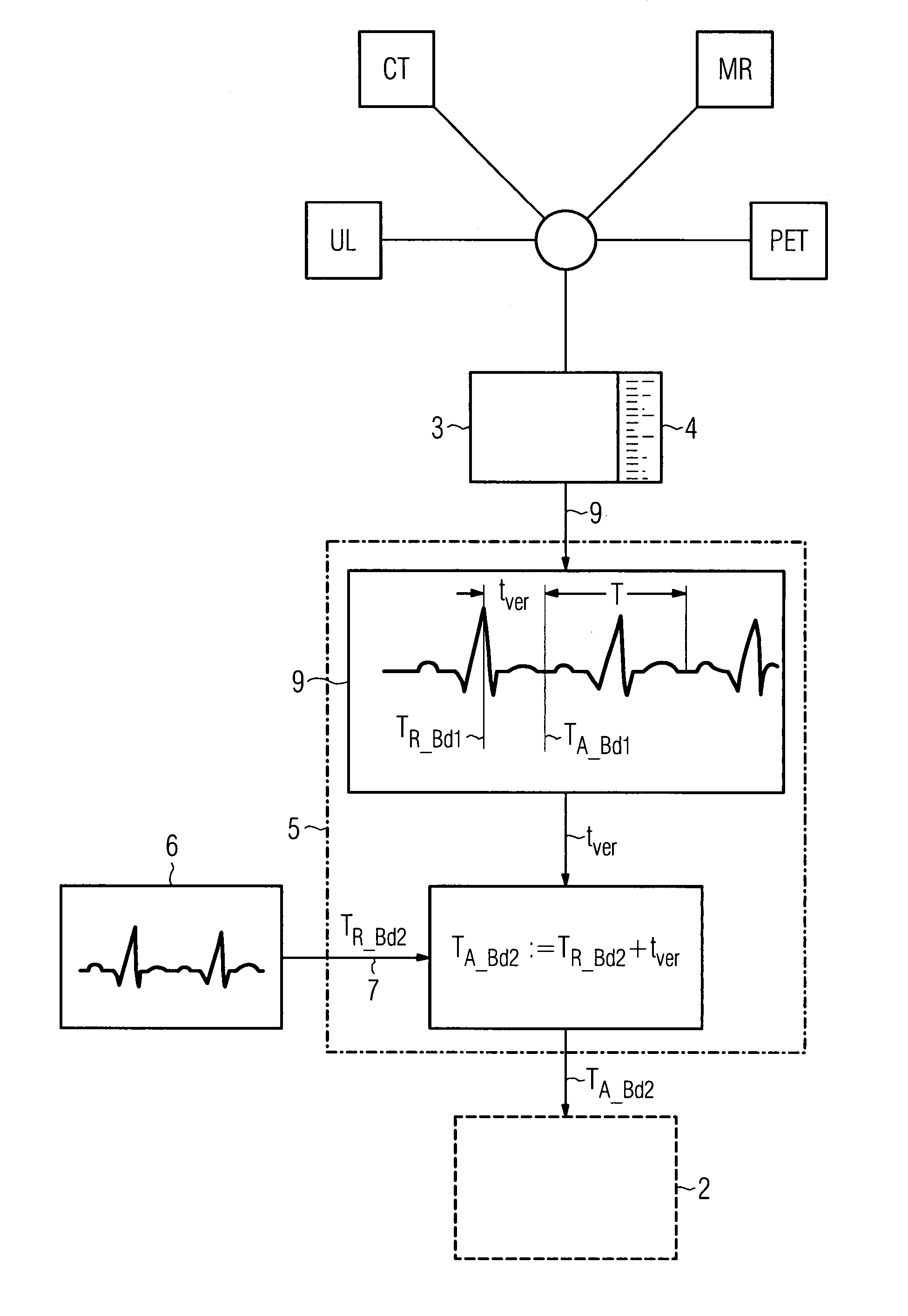
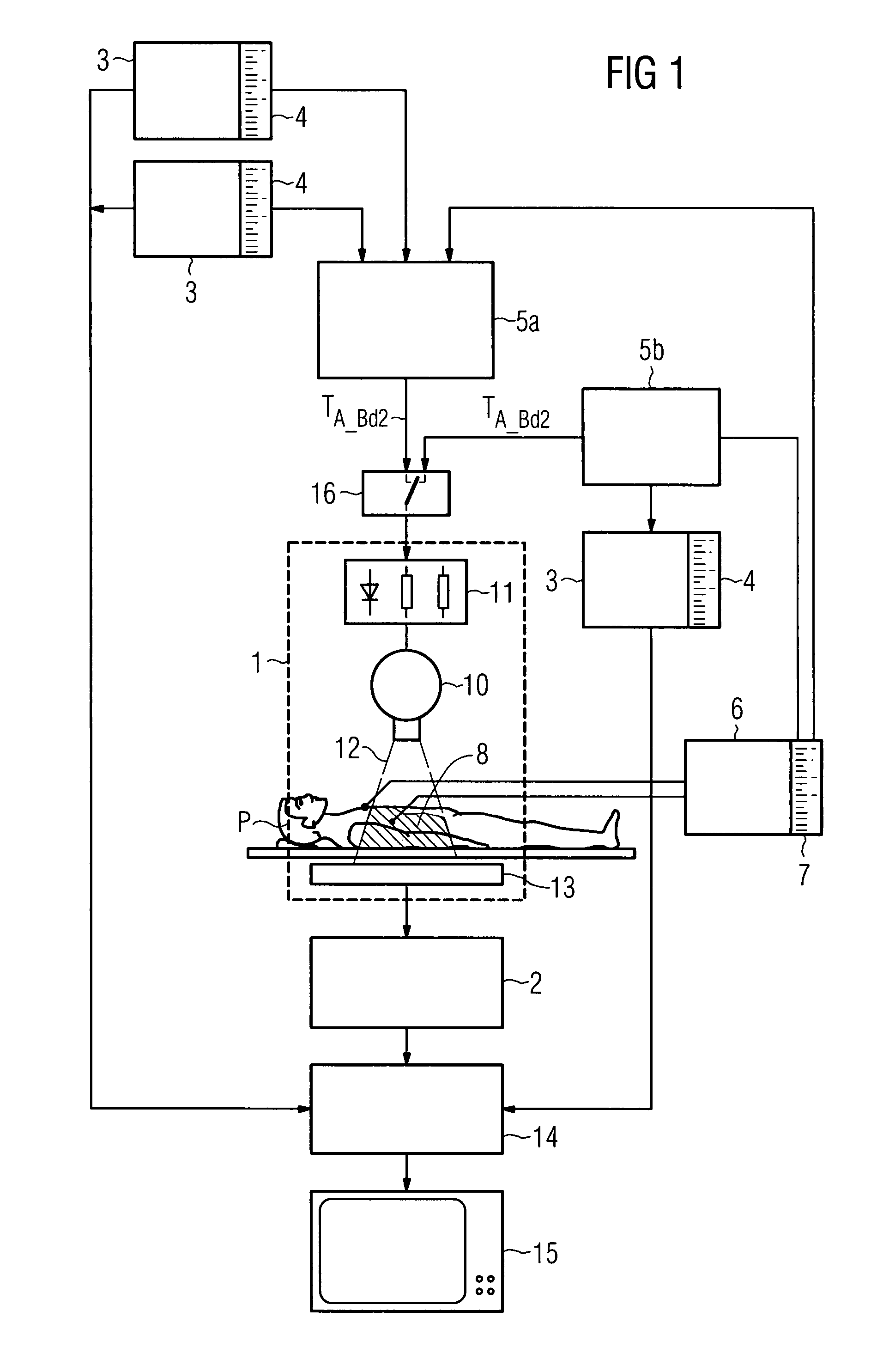
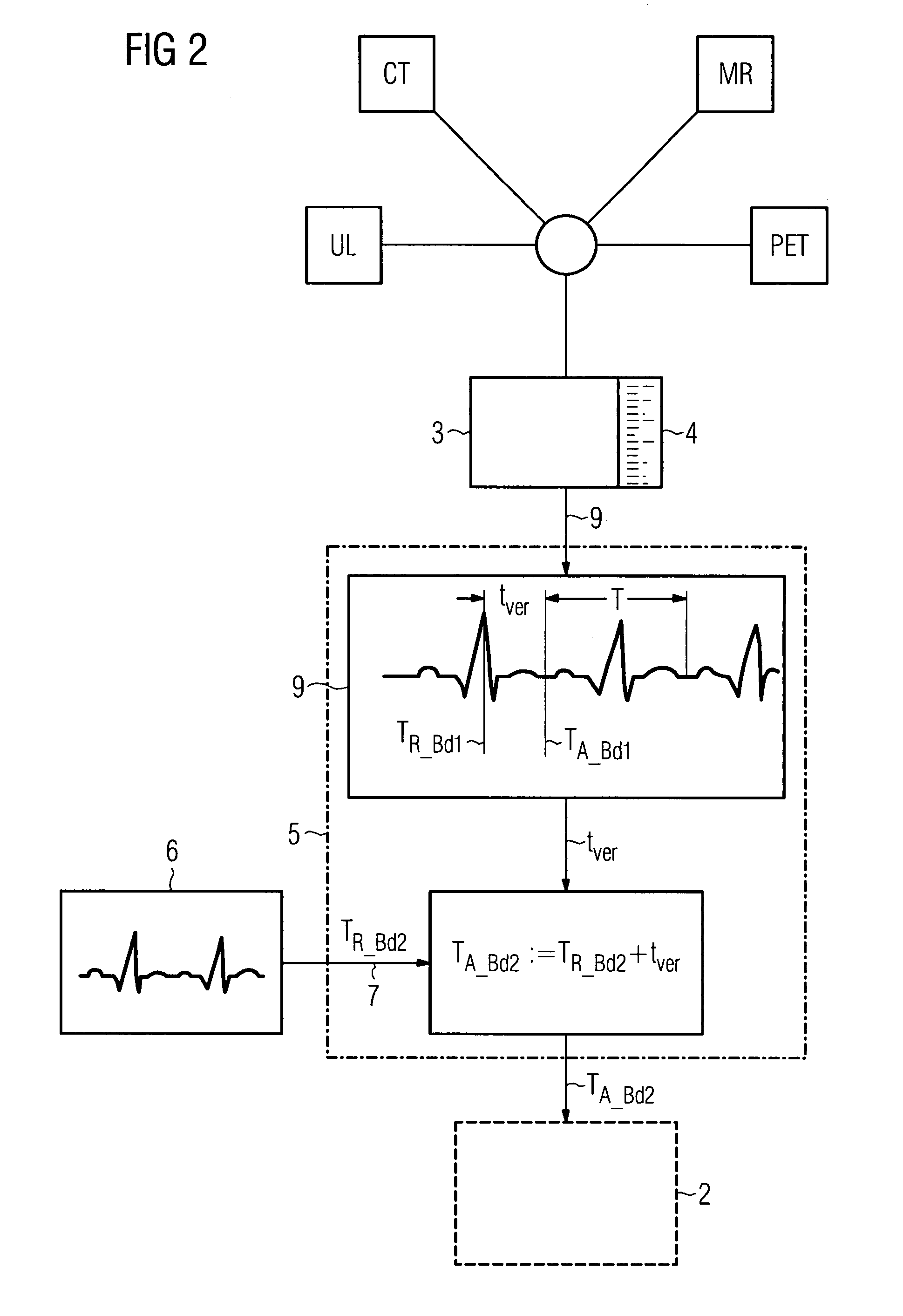
[0025]The image capture device 1 shown in FIG. 1 is used for recording a second image data set 2 of a patient P that is synchronized to a first image data set 3. An x-ray tube 10 is operated by an x-ray generator 11. The x-ray tube 10 emits an x-ray beam 12 which passes through a patient P in the area under examination 8 and is incident on an x-ray detector 13 in attenuated form depending on the transparency of the patient P and creates an x-ray image. The absorption of the x-radiation 12 by the patient P follows an exponential function. The x-ray detector 13 converts the x-ray image into electrical signals and produces a second image data set 2. In an associated digital image processing system 14, the second image data set 2 and the first, generally pre-operative image data set 3 are processed and made available to one or more output units 15 to reproduce an overlaid image. In order that the image capture device 1 then only generates recordings that are in synchronism with the firs...


PUM


Abstract

The present invention relates to a device and a method for synchronizing an image capture device with a first image data set. The image capture device is used for recording a second image data set of a periodically moving area or object. Each first image data set contains information as to the point in time, relative to the periodically moving area or object, when recording took place. The device additionally acquires periodically recurring, current information of the area as well as information concerning the recording instant of the first image data set. From the periodically recurring information and the recording instant of the first image data set, a triggering instant is derived which controls at least one recording of the second image data set by the image capture device in such a way that the second image data set contains image data synchronized to the first image data set.

Description

CROSS REFERENCE TO RELATED APPLICATIONS[0001]This application claims priority of German application No. 10 2006 013 475.3 filed Mar. 23, 2006, which is incorporated by reference herein in its entirety.FIELD OF THE INVENTION[0002]The present invention relates to a device and method for synchronizing an image capture device with a first image data set. The image capture device is used for recording a second image data set of a periodically moving area or periodically moving object. Each first image data set contains information as to the point in time, relative to the periodically moving area or object, when recording took place. The device also has means of acquiring periodically recurring, current information of the area as well as information concerning the recording instant of the first image data set.BACKGROUND OF THE INVENTION[0003]In medical engineering, for example, image-assisted interventional methods have long played an important role. This applies particularly to surgical ...

Claims


Application Information

Patent Timeline
Patent Type & Authority Patents(United States)
IPC IPC(8): G06K9/00A61B5/352
CPCA61B6/541A61B19/52A61B5/7285A61B6/503A61B2019/5289A61B19/5225A61B2019/5214A61B90/36A61B2090/3612A61B2090/364A61B90/37
Inventor BOESE, JANMEYER, ANDREASRAHN, NORBERTSANDKAMP, BERNHARD
Owner SIEMENS HEALTHCARE GMBH
Why Eureka
Try Eureka