
Arterial flashback confirmation chamber

a flashback confirmation and chamber technology, applied in the field of vascular access devices, can solve the problems of operator being at risk of being exposed to high-pressure arterial blood, operator not being able to observe additional blood flowing into the assembly, operator not being able to visually confirm a reduction of blood flow into the catheter and extension tube,

Active Publication Date: 2013-04-02
BECTON DICKINSON & CO
View PDF22 Cites 64 Cited by
  • Summary
  • Abstract
  • Description
  • Claims
  • Application Information

AI Technical Summary

Benefits of technology

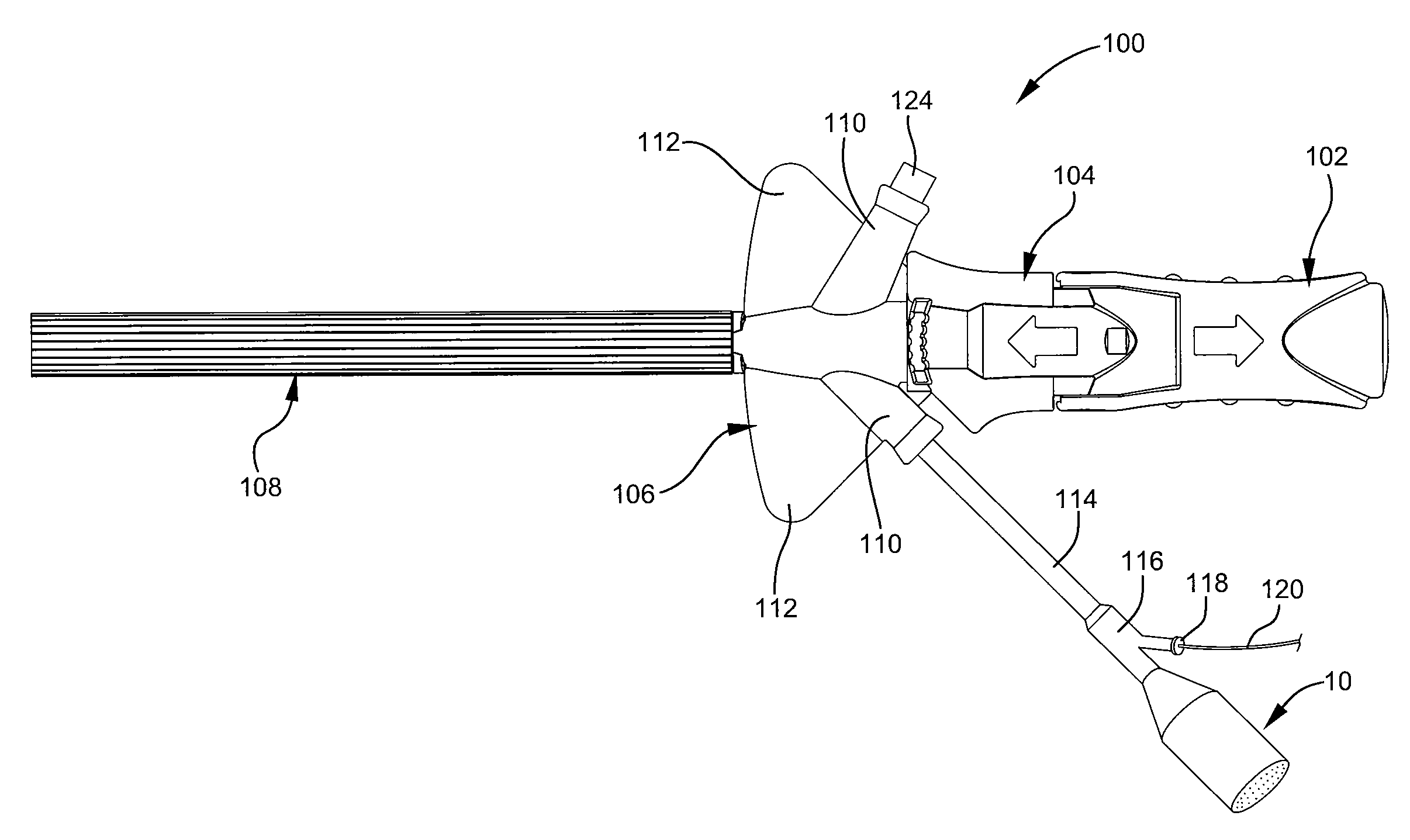
[0008]The present invention relates to an arterial flashback confirmation chamber, or a confirmation chamber, that is designed to overcome the limitations mentioned above. Indeed, in some instances, the described arterial flashback confirmation chamber is configured to allow an operator to see active arterial flashback confirmation for a longer period of time than would be possible with a conventional catheter assembly in which the operator simply observes flashback within the catheter and extension tube. Accordingly, the described flashback confirmation chamber can allow the operator to watch blood actively flow into the flashback compartment for a period of time that is sufficient to allow the operator to carefully and properly place the needle and catheter tip within a patient's artery.
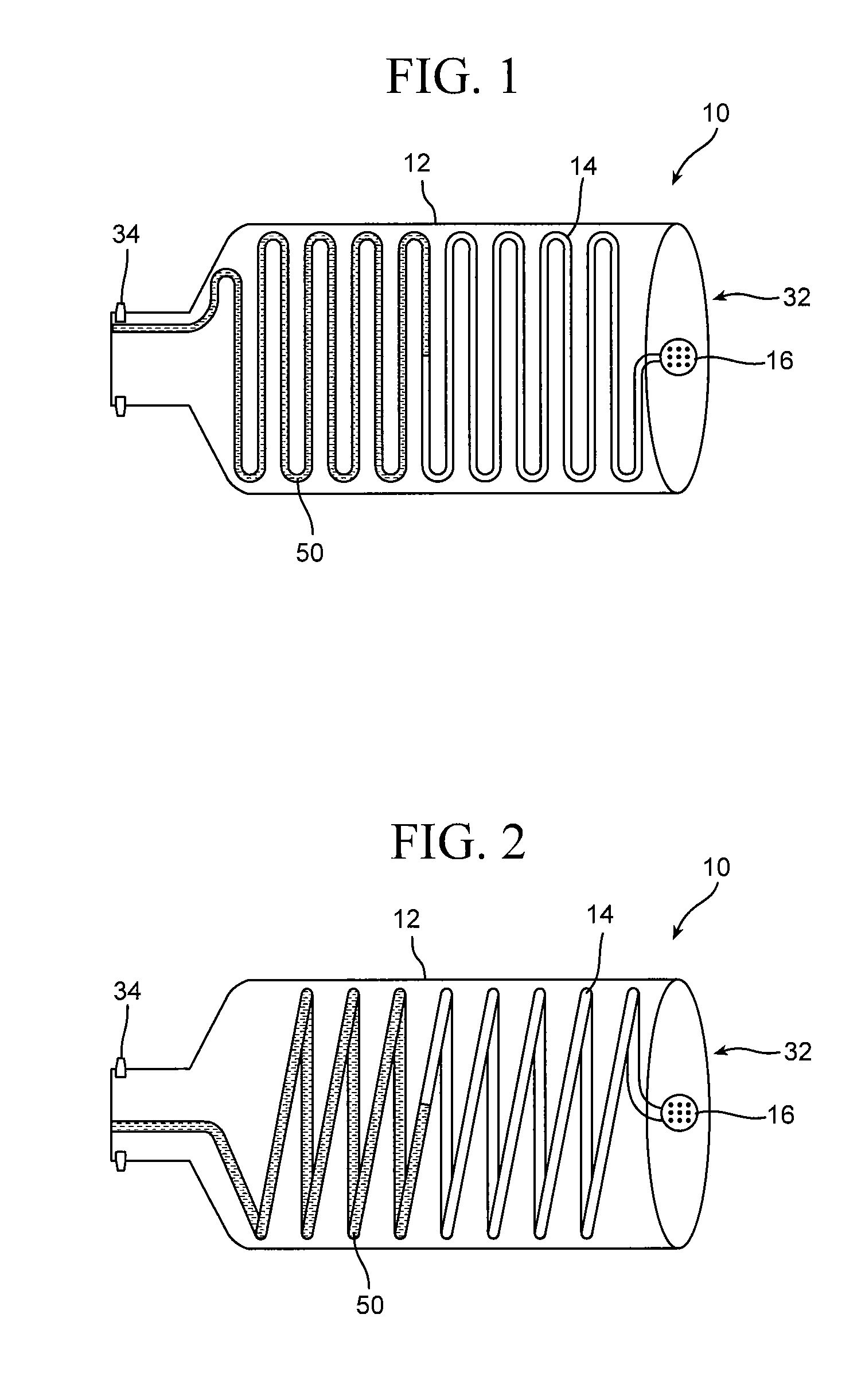
[0011]The means for prolonging active arterial flashback confirmation may comprise any component or characteristic that allows an operator to see active arterial flashback confirmation in the flashback compartment for a period of time that is long enough to allow the operator to properly and carefully place the needle within a patient's artery. Some examples of suitable prolonging means comprise a flashback compartment with a relatively large internal volume, circuitous tubing, an absorbent material, an orifice or tubing with an inner diameter that is smaller than an inner diameter of the cannula of the vascular access device, and / or another component or characteristic that is capable of prolonging the amount of time during which an operator can see active arterial flashback confirmation.
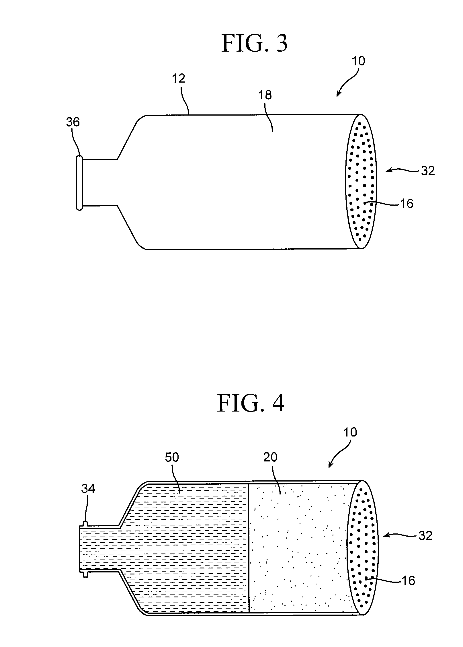
[0012]Where the prolonging means comprises a flashback compartment with a relatively large internal volume, the prolonging means may increase the time in which the operator can observe the active arterial flashback by allowing more blood to enter the compartment than is possible in certain conventional catheter assemblies that lack the described confirmation chamber. Accordingly, the flashback compartment may have any suitable internal volume that allows it to fulfill its intended purpose. In one example, the compartment has an internal volume between about 1 cubic centimeters (“cc”) and about 500 cc. In another example, the volume of the compartment is from about 3 cc to about 100 cc. In still another example, the internal volume of the compartment is from about 5 cc to about 15 cc.

Problems solved by technology

In one example, some conventional catheter assemblies may place the operator at risk of being exposed to high-pressure arterial blood.
In another example, while some catheter assemblies allow blood to flow from a low-pressure vein into the catheter and extension tube for a relatively long period of time, the same assemblies may only allow blood to flow from an artery, with a higher pressure than the vein, for a relatively short time period before the blood completely fills the catheter and extension tube.
As a result, the operator may not be able to observe additional blood flowing into the assembly for a period of time that is sufficient to allow the operator to carefully and properly place the needle within the artery.
For instance, once arterial blood fills the catheter and extension tube, the operator may not visually confirm a reduction of blood flow into the catheter and extension tube when the operator pushes the needle tip completely through the artery.
As a result, the operator of certain conventional catheter assemblies may have difficulty determining proper needle and catheter placement within arteries.

Method used


Image

  • Arterial flashback confirmation chamber
  • Arterial flashback confirmation chamber
  • Arterial flashback confirmation chamber

Examples


Embodiment Construction

[0030]The presently preferred embodiments of the described invention will be best understood by reference to the Figures, wherein like reference numbers indicate identical or functionally similar elements. It will be readily understood that the components of the present invention, as generally described and illustrated in the Figures, could be arranged and designed in a wide variety of different configurations. Thus, the following more detailed description, as represented in FIGS. 1 through 8, is not intended to limit the scope of the invention as claimed, but is merely representative of some presently preferred embodiments of the invention.

[0031]This disclosure describes an arterial flashback confirmation chamber that can be added to a vascular access device to prolong the period of time in which an operator may observe active arterial flashback confirmation from the assembly. As used herein, the term active arterial flashback confirmation may refer to the act of blood continuously...


PUM


Abstract

The present invention relates to an arterial flashback confirmation chamber. Generally, the confirmation chamber is used with a vascular access device to allow an operator to see active arterial flashback confirmation for a period of time that is long enough to permit the operator to properly place the cannula of the vascular access device within a patient's artery. In some instances, the confirmation chamber comprises a flashback compartment, means for prolonging active arterial flashback confirmation, and a vent. Some examples of suitable prolonging means comprise a flashback compartment with a relatively large internal volume, circuitous tubing, an absorbent material, an orifice and / or tubing with a smaller inner diameter than the inner diameter of the cannula, and the like. Where the vascular access device comprises a catheter assembly, the catheter assembly and confirmation camber are optionally used with a guide wire and / or a blood sensor.

Description

BACKGROUND OF THE INVENTION[0001]The present invention relates to vascular access devices. More specifically, the present invention relates to an arterial flashback confirmation chamber that is configured to be attached to a vascular access device and to allow an operator to see arterial blood flashback confirmation for a prolonged period of time after the operator punctures an artery with a cannula from the access device.[0002]Generally, vascular access devices are used for communicating fluid with the vascular system of patients. In one example, catheters are used for infusing fluid (e.g., saline solution, medicaments, and / or total parenteral nutrition) into a vein and / or withdrawing fluids (e.g., blood) from a vein. In another example, a catheter is inserted into a patient's artery (e.g., radial, brachial, femoral, pedal, carotid artery, etc.) to monitor blood pressure in real-time, to obtain samples for arterial blood gas measurements, to withdraw blood, and / or to deliver fluids...

Claims


Application Information

Patent Timeline
Patent Type & Authority Patents(United States)
IPC IPC(8): A61M5/32A61B5/055
CPCA61M25/0693
Inventor SONDEREGGER, RALPH L.
Owner BECTON DICKINSON & CO
Learn More