Method and apparatus to measure bioelectric impedance of patient tissue

a bioelectric impedance and tissue technology, applied in the field of patient monitoring, can solve the problems of not accurately measuring the impedance, unable to provide as much accuracy, and the electronic devices used to measure the complex impedance signals of the patient may be somewhat larger than ideal, so as to minimize errors, eliminate a time-consuming step at manufacture, and minimize the memory resources of the controlling computer and/or processor

Active Publication Date: 2013-04-02
MEDTRONIC MONITORING
View PDF751 Cites 229 Cited by
  • Summary
  • Abstract
  • Description
  • Claims
  • Application Information

AI Technical Summary

Benefits of technology

[0008]In many embodiments of the present invention, tissue impedance is determined in response a calibration signal from calibration circuitry and a tissue impedance signal from the tissue. Because the tissue impedance can be determined from both a tissue impedance signal and a calibration signal, errors can be minimized, for example errors that correspond to fluctuations in drive current, variations in measurement circuitry gain, time delays of the drive circuitry, time delays of the measurement circuitry, and parasitic impedance of the tissue, for example skin. The drive circuitry can be coupled to the calibration circuitry and at least two drive electrodes so as to drive current through the tissue and the calibration circuitry. Thus, a calibration signal from the calibration circuitry can be measured when the electrodes are connected to the patient, such that the calibration signal substantially corresponds to the current actually delivered through the tissue. Measurement circuitry can be connected to at least two measurement electrodes so as to measure a tissue impedance signal in response to the impedance of the tissue and the current through the tissue. The measurement circuitry can also be coupled to the calibration circuitry to measure the calibration signal, such that the tissue impedance can be determined in response to the measured calibration signal and the measured tissue impedance signal. Processor circuitry comprising a tangible medium can be configured to determine a complex tissue impedance in response to the calibration signal and the tissue impedance signal, such errors are minimized which correspond to fluctuations in drive current, variations in measurement circuitry gain, time delays of the drive circuitry, time delays of the measurement circuitry, and parasitic impedance of the tissue. As the calibration resistor can be provided with the drive circuitry and measurement circuitry, the system can be self calibrating, thereby eliminating a time consuming step at manufacture and minimizing memory resources of the controlling computer and / or processor. In many embodiments, the processor can be configured to select a frequency for the drive current, and the drive circuitry can be configured to increase the amount of drive current with increasing frequency, such that the signal to noise ratio can be improved. The amount of drive current at a selected increased frequency may even exceed a safety threshold for the amount of drive current at a lower frequency. The measurement circuitry can be configured to decrease the gain of the impedance signal with increasing frequency, such that the increased amount of current does not saturated the measurement circuitry and / or digitization electronics such as an analog to digital converter.

Problems solved by technology

Some current devices may not accurately measure the impedance of the internal tissue of the patient, thereby making accurate hydration measurements more difficult.
The electronics used to measure complex impedance signals of the patient may be somewhat larger than ideal and may not provide as much accuracy as would be ideal.
Thus, devices that are worn by the patient may be somewhat uncomfortable, which may lead to patients not wearing the devices and not complying with direction from the health care provider, such that data collected may be less than ideal.
Although implantable devices may be used in some instances, many of these devices can be invasive and / or costly, and may suffer at least some of the shortcomings of known wearable devices described above.
In addition, implantable devices can be invasive and / or costly such that many patients cannot receive a therapeutic benefit.
Although injectable devices may decrease invasiveness, the size requirements of injectable devices can place limitations on the circuitry and may limit the accuracy of such devices.

Method used


Image

  • Method and apparatus to measure bioelectric impedance of patient tissue
  • Method and apparatus to measure bioelectric impedance of patient tissue
  • Method and apparatus to measure bioelectric impedance of patient tissue

Examples


Embodiment Construction

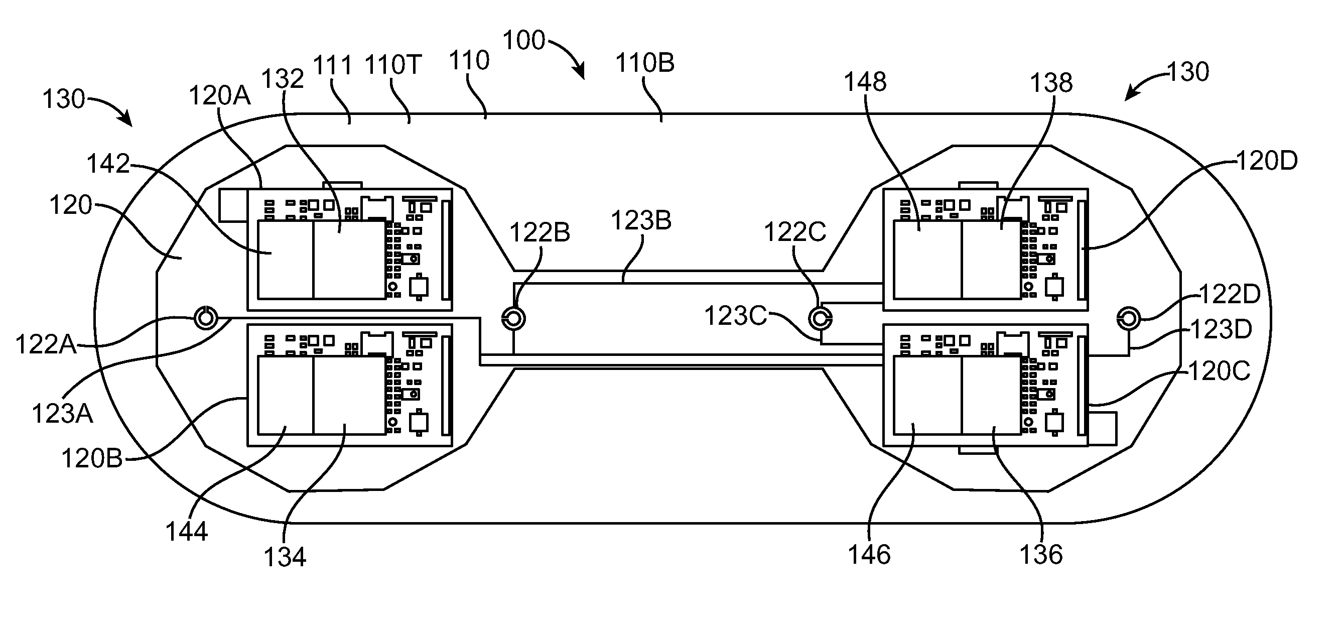
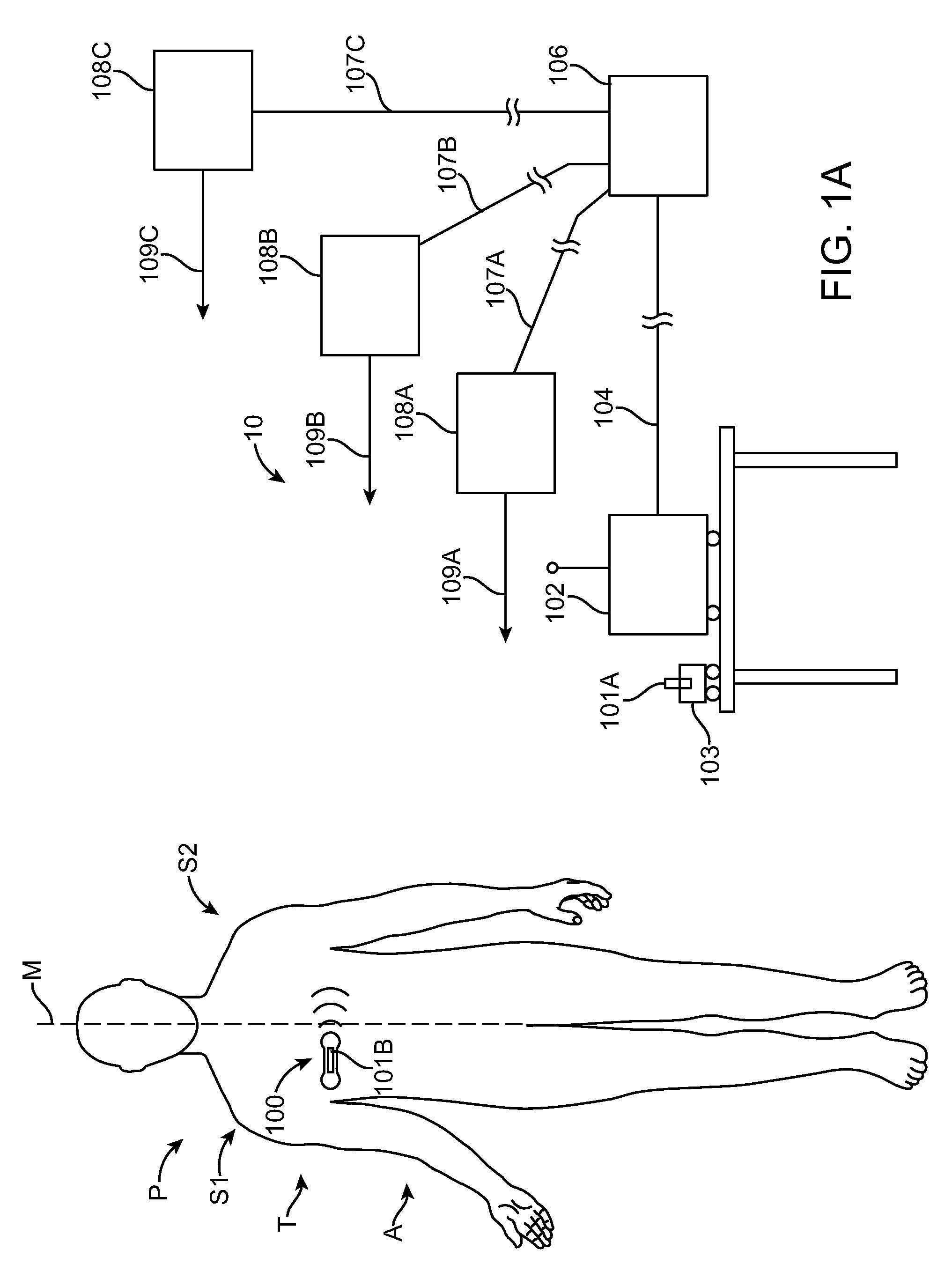
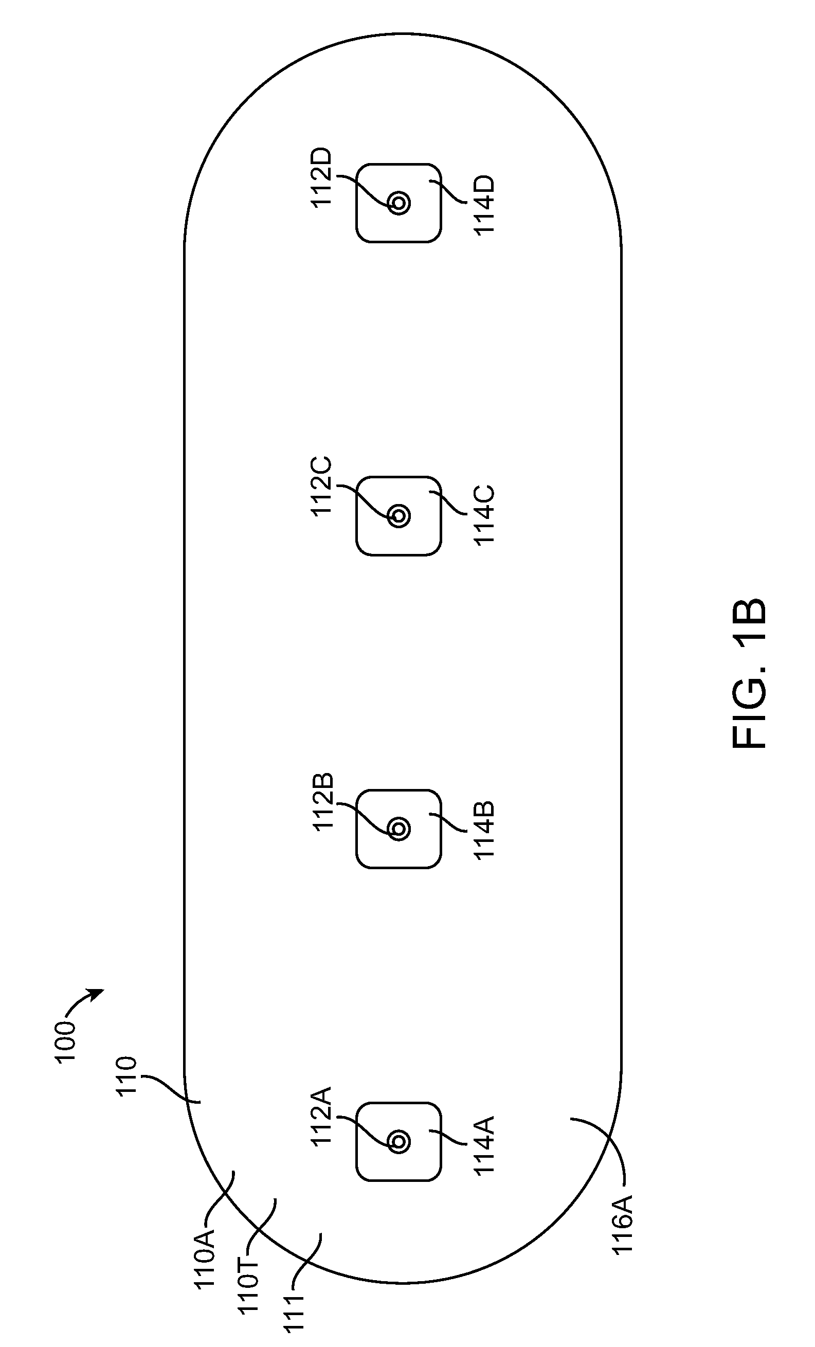
[0043]Embodiments of the present invention relate to patient monitoring. Although embodiments make specific reference to monitoring impedance and electrocardiogram signals with an adherent patch, the system methods and device described herein may be applicable to many application in which physiological monitoring is used, for example physiological monitoring with implantable devices.

[0044]In many embodiments, the adherent devices described herein may be used for 90 day monitoring, or more, and may comprise completely disposable components and / or reusable components, and can provide reliable data acquisition and transfer. In many embodiments, the patch is configured for patient comfort, such that the patch can be worn and / or tolerated by the patient for extended periods, for example 90 days or more. In many embodiments, the adherent patch comprises a tape, which comprises a material, preferably breathable, with an adhesive, such that trauma to the patient skin can be minimized while ...


PUM


Abstract

A device to measure tissue impedance comprises drive circuitry coupled to calibration circuitry, such that a calibration signal from the calibration circuitry corresponds to the current delivered through the tissue. Measurement circuitry can be coupled to measurement electrodes and the calibration circuitry, such that the tissue impedance can be determined in response to the measured calibration signal from the calibration circuitry and the measured tissue impedance signal from the measurement electrodes. Processor circuitry comprising a tangible medium can be configured to determine a complex tissue impedance in response to the calibration signal and the tissue impedance signal. The processor can be configured to select a frequency for the drive current, and the amount of drive current at increased frequencies may exceed a safety threshold for the drive current at lower frequencies.

Description

CROSS-REFERENCES TO RELATED APPLICATIONS[0001]The present application claims the benefit under 35 USC 119(e) of U.S. Provisional Application No. 61 / 046,221 filed Apr. 18, 2008; the full disclosure of which is incorporated herein by reference in its entirety.BACKGROUND OF THE INVENTION[0002]The present invention relates to patient monitoring. Although embodiments make specific reference to monitoring impedance and electrocardiogram signals with an adherent patch, the system methods and device described herein may be applicable to many applications in which physiological monitoring is used, for example physiological monitoring with implantable devices.[0003]Patients are often treated for diseases and / or conditions associated with a compromised status of the patient, for example a compromised physiologic status. In some instances, a patient may report symptoms that require diagnosis to determine the underlying cause. For example, a patient may report fainting or dizziness that requires...

Claims


Application Information

Patent Timeline
Patent Type & Authority Patents(United States)
IPC IPC(8): A61B5/00A61B5/308
CPCA61B5/0531A61B5/0205A61B5/04085A61B5/0809A61B5/04087A61B5/0428A61B5/0006A61B5/0002A61B5/0402A61B5/7257A61B7/00A61B2560/0223A61B5/318A61B5/259A61B5/30A61B5/282
Inventor MAZAR, SCOTT T.
Owner MEDTRONIC MONITORING
Why Eureka
Try Eureka