
Frequency synthesizer for a level measuring device and a level measuring device

a level measuring device and frequency synthesizer technology, applied in the field of frequency synthesizers, can solve the problems of comparatively high circuitry cost, circuits being comparatively complex, and the approach to implementing a frequency synthesizer using two direct digital synthesizers is comparatively costly, so as to achieve attenuation or suppress the effect of phase resolution

Active Publication Date: 2013-04-09
KROHNE MESSTECHNICK GMBH & CO KG
View PDF28 Cites 4 Cited by
  • Summary
  • Abstract
  • Description
  • Claims
  • Application Information

AI Technical Summary

Benefits of technology

[0016]Therefore, a primary object of this invention is to provide a frequency synthesizer and a level measuring device using direct digital synthesizers which avoids the aforementioned disadvantages, at least in part.

Problems solved by technology

For sampling of reflected microwaves with the associated short signal transmit times, this necessitates sampling frequencies which can be managed only with exceedingly high circuitry cost.
Known frequency synthesizers generally work with phase locked loops with which certain phases and frequency shifts that can be set, these circuits being comparatively complex since they require, for example, tunable oscillators (for example, VCO).
Aside from the fact that the approach to implementing a frequency synthesizer using two direct digital synthesizers is comparatively costly, it also has technical disadvantages which are related to the spectral interference which is conventionally produced by direct digital synthesizers.

Method used


Image

  • Frequency synthesizer for a level measuring device and a level measuring device
  • Frequency synthesizer for a level measuring device and a level measuring device
  • Frequency synthesizer for a level measuring device and a level measuring device

Examples


Embodiment Construction

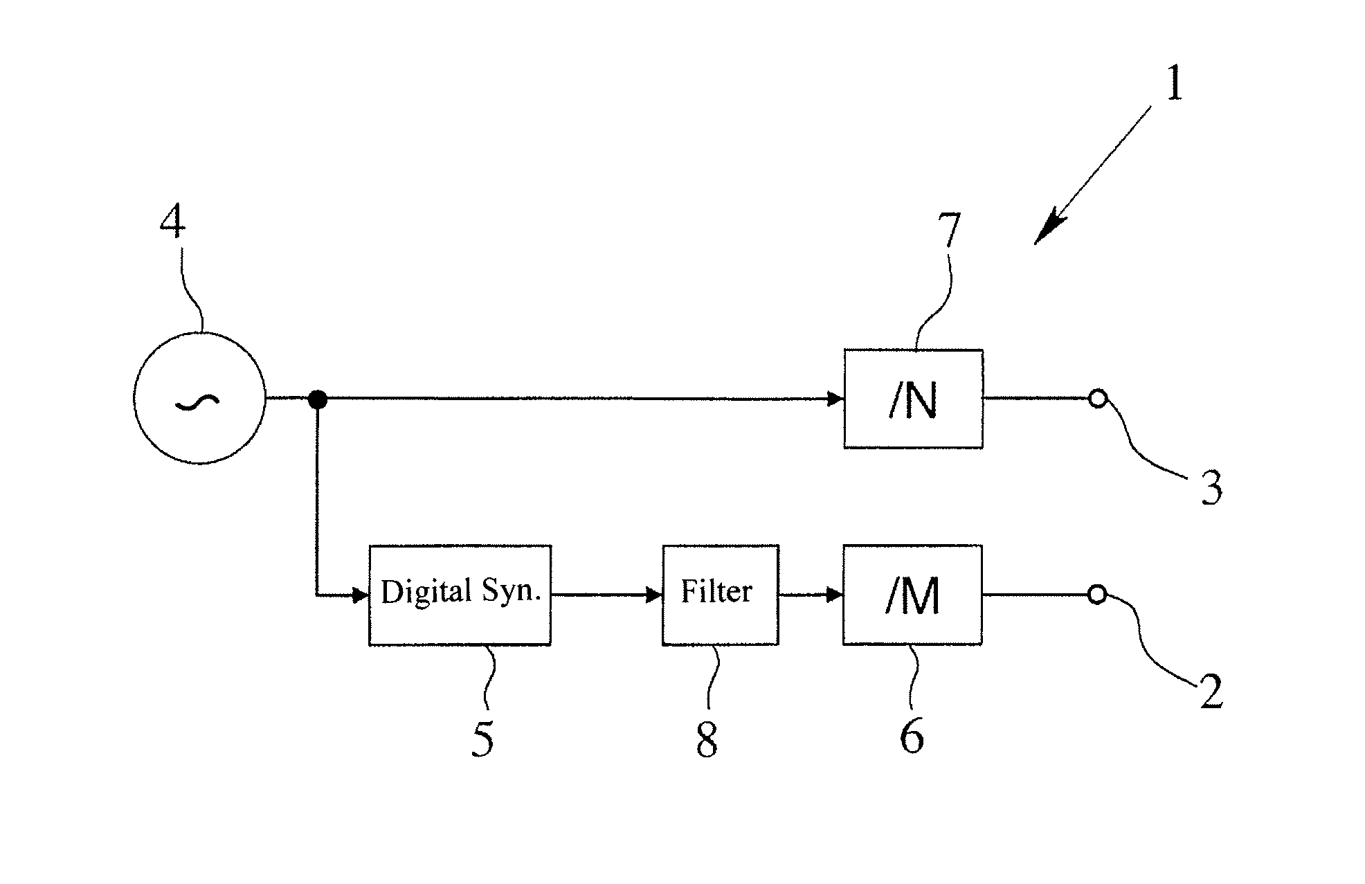
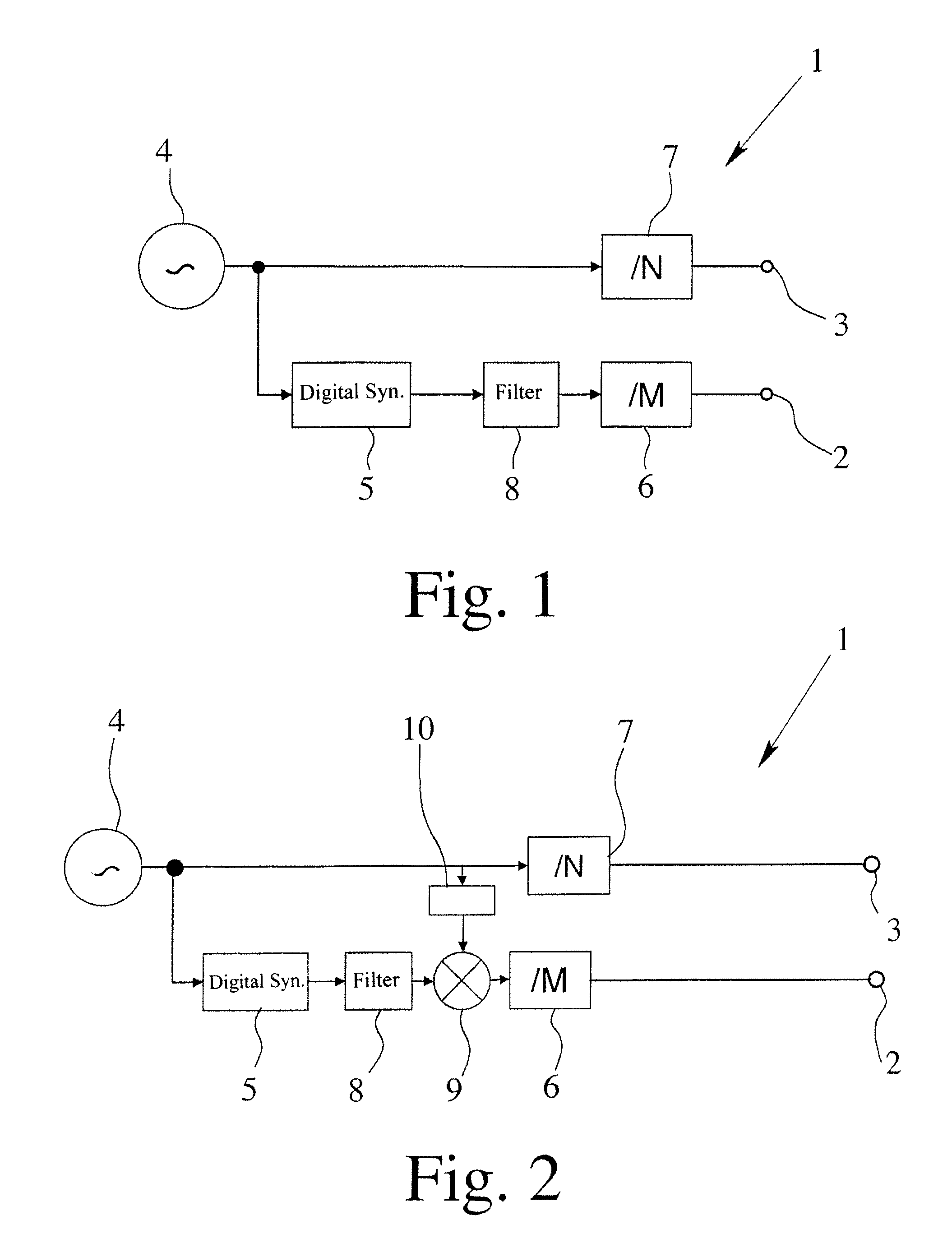
[0032]The frequency synthesizers 1 which are shown in FIGS. 1 and 2 are intended for a time base generator of a level measuring device which is not detailed and which works according to the radar principle. It is common to frequency synthesizers 1 that they have a first output 2 for output of a first frequency signal and a second output 3 for output of a second frequency signal. Furthermore they each have a reference oscillator 4 for producing a reference frequency signal. The first frequency signal and the second frequency signal have a small difference frequency of a few hertz relative to one another, thus as is required, for example, to implement slow motion serial sampling, as was described at the beginning. It is also common to the illustrated frequency synthesizers 1 that the first frequency signal can be produced at the first output 2 by interaction of the reference oscillator 4 with a first direct digital synthesizer 5 by specifically the first direct digital synthesizer 5 b...


PUM


Abstract

A frequency synthesizer for a time base generator of a level measuring device which works according to the radar principle, with at least one first output for output of a first frequency signal, with at least one second output for output of a second frequency signal, and with a reference oscillator for producing a reference frequency signal, the first frequency signal and the second frequency signal having a small difference frequency relative to one another, the first frequency signal being producible by interaction of the reference oscillator with a direct digital synthesizer. The first frequency signal and second frequency signal can be generated with especially low noise by the second frequency signal being derived from the reference oscillator without interconnection of a direct digital synthesizer and the direct digital synthesizer being operated such that only a noise spectrum is produced which is at least partially minimized.

Description

BACKGROUND OF THE INVENTION[0001]1. Field of the Invention[0002]The invention relates to a frequency synthesizer, especially for a time base generator of a level measuring device which works according to the radar principle, with at least one first output for outputting of a first frequency signal, with at least one second output for outputting of a second frequency signal, and with a reference oscillator for producing a reference frequency signal, the first frequency signal and the second frequency signal having a small difference frequency relative to one another, the first frequency signal being producible by interaction of the reference oscillator with a direct digital synthesizer. Furthermore, the invention also relates to a level measuring device which works according to the radar principle with a frequency synthesizer for producing a first frequency signal—sampling signal—and for producing a second frequency signal—transmission signal.[0003]2. Description of Related Art[0004]...

Claims


Application Information

Patent Timeline
Patent Type & Authority Patents(United States)
IPC IPC(8): G01S13/08
CPCG06F1/0328H03B19/00H03B21/02
Inventor GERDING, MICHAEL
Owner KROHNE MESSTECHNICK GMBH & CO KG
Learn More