Distributed turbo coding and relaying protocols

a technology of distributed turbo and relaying protocols, which is applied in the direction of code conversion, frequency-division multiplex, etc., can solve the problem that it is not possible for mobile terminals or wireless sensor nodes to equip with multiple transmit antennas, and achieve the best transmit signal-to-noise ratio (snr), facilitate system design, and improve system performance and capacity.

Inactive Publication Date: 2013-04-09
THE UNIV OF SYDNEY
View PDF7 Cites 7 Cited by
  • Summary
  • Abstract
  • Description
  • Claims
  • Application Information

AI Technical Summary

Benefits of technology

[0019]The received signals may be combined so as to maximise the Signal-to-Noise Ratio (SNR) of the combined signal.
[0040]The invention takes advantages of both the DAF and AAF protocols but minimise their negative affects. AAF-only protocols usually suffer from noise amplification while DAF-only protocols propagate error through imperfect decoding when channel quality from the source to the relay is poor. Using the invention, the relaying protocol is automatically adapted to the channel quality by simply switching between the AAF and the DAF without any need for the channel state information (CSI) to be fed back from the destination to the relays or the source. This is very important in practical relay networks, especially in a multi-hop large network, in which the feedback of CSI for adaptation is very expensive.
[0041]Additionally, adaptive relaying with relay selection facilitates system design for non-orthogonal channels and may improve system performance and capacity. By requiring only the signal from the relay having the best transmit Signal-to-Noise Ratio (SNR), other relays in the network do not have to relay the signal. Since channels may not be perfectly orthogonal in practice, this strategy reduces interference to the best relay, source and destination. Besides, other relays may conserve battery power by not having to relay signals when channel quality between the relays and the destination is poor.

Problems solved by technology

However, in a cellular network or wireless sensor networks, due to the limited size, cost and hardware limitation, it may not be possible for a mobile terminal or wireless sensor nodes to equip with multiple transmit antennas.

Method used


Image

  • Distributed turbo coding and relaying protocols
  • Distributed turbo coding and relaying protocols
  • Distributed turbo coding and relaying protocols

Examples


Embodiment Construction

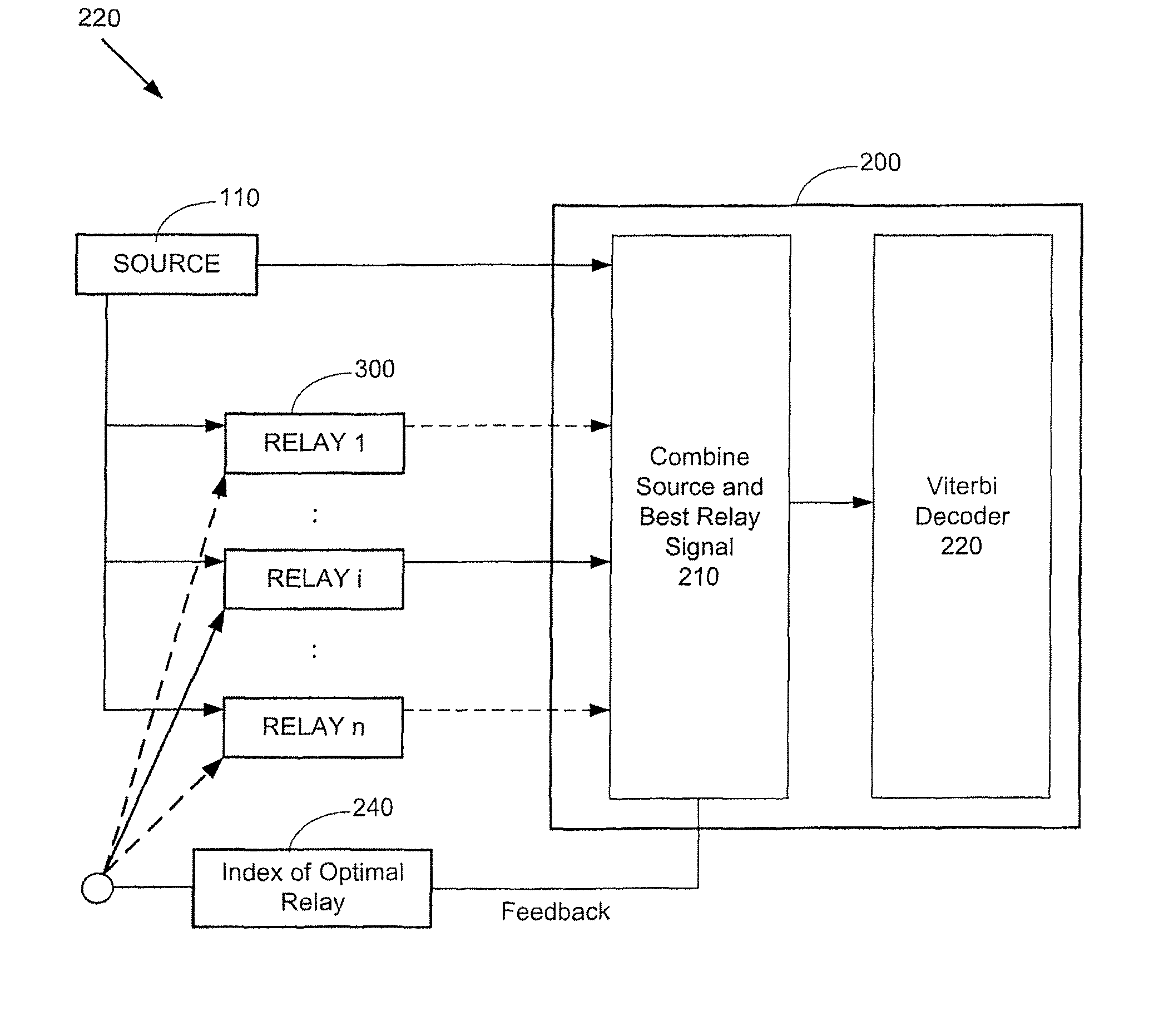
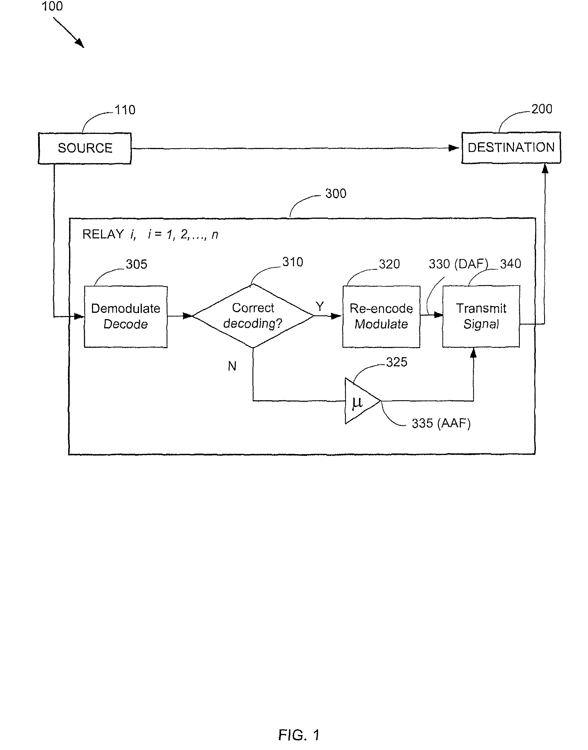
[0057]Referring first to FIG. 1, we consider a general 2-hop relay network 100, consisting of one source 110, n relays 300 and one destination 200 with a direct link from the source 110 to the destination 200. There may be more than one relay between the source 110 and the destination 200, forming a multi-hop network.

[0058]At the source 110, the transmitted source information binary stream, denoted by B, is represented by

B=(b(1), . . . , b(k), . . . , b(l))  (1)

where b(k) is a binary symbol transmitted at time k and l is the frame length.

[0059]The binary information sequence B is first encoded by a channel encoder. For simplicity, we consider a recursive systematic convolutional code (RSCC) with a code rate of 1 / 2. Let C represent the corresponding codeword, given by

C=(C(1), . . . C(k), . . . , C(l))  (2)

where C(k)=(b(k), c(k) is the codeword of b(k), c(k)ε{0, 1}, b(k) is the information symbol and c(k) is the corresponding parity symbol.

[0060]The binary symbol stream C is then mapp...


PUM


Abstract

This invention concerns distributed turbo coding and relaying protocols in wireless relay networks. In particular, the invention concerns a method for relaying signals at a relay node, a method for processing signals at a destination node, a relay system and software to perform the methods. The wireless relay networks comprise a source node, a destination node and one or more relay nodes. At a relay node, the invention comprises the steps of receiving a signal from a first node; decoding the received signal; and if the received signal is decoded incorrectly, employing an Amplify-And-Forward (AAF) relaying protocol comprising the steps of amplifying the received signal and then transmitting the amplified signal to a second node; but otherwise, employing a Decode-And-Forward (DAF) relaying protocol comprising the steps of re-encoding the decoded signal and then transmitting the coded signal to the second node. At a destination node, data transmitted by the source node is recovered by combining all signals received from the source and relay nodes and then decoding the combined signal.

Description

CROSS-REFERENCE TO RELATED APPLICATION[0001]This application is a continuation of International Application Serial No. PCT / AU2007 / 001729, filed Nov. 9, 2007, pending, which claims priority under Section 119 to AU 2007901330 filed Mar. 14, 2007 and AU 2007902931 filed May 31, 2007.TECHNICAL FIELD[0002]This invention concerns distributed turbo coding and relaying protocols in wireless relay networks. In particular, the invention concerns a method for relaying signals at a relay node, a method for processing signals at a destination node, a relay system and software to perform the methods.BACKGROUND ART[0003]In wireless communication systems, diversity has been an effective technique in combating detrimental effects of channel fading caused by multi-path propagation and Doppler shift. Specifically, a spatial diversity can be achieved by a multiple-input-multiple-output (MIMO) system by exploiting space time coding. However, in a cellular network or wireless sensor networks, due to the ...

Claims


Application Information

Patent Timeline
Patent Type & Authority Patents(United States)
IPC IPC(8): H04B7/14
CPCH04B7/15557H03M13/09H03M13/2957
Inventor VUCETIC, BRANKALI, YONGHUI
Owner THE UNIV OF SYDNEY
Why Eureka
Try Eureka