Transmitting device and method for determining target predistortion setting value

a technology of transmitting device and setting value, which is applied in the field of transmitting device, can solve the problems of complex algorithms, high cost, and poor linearity of power amplifier, and achieve the effects of improving the accuracy of the signal

Active Publication Date: 2013-04-09
REALTEK SEMICON CORP
View PDF4 Cites 0 Cited by
  • Summary
  • Abstract
  • Description
  • Claims
  • Application Information

AI Technical Summary

Benefits of technology

[0008]Briefly summarized, the present invention can predistort signals before a power amplifier in a transmitting device by a method of determining a target predistortion setting value (i.e. an optimal predistortion setting value) from a plurality of candidate predistortion setting values. In this way, signals outputted by the power amplifier in the transmitting device can be adjusted to an optimal state, so as to solve the distortion problem of the outputted signals of the power amplifier.

Problems solved by technology

However, the power amplifier has a worse linearity when a larger power is inputted, and thus the amplified output signal has a distortion problem.
In general, the predistortion unit and related method utilized to solve the distortion problem of the power amplifier of the transmitting device in the prior art requires complicated algorithms and high cost.
Therefore, how to provide a transmitting device comprising a predistortion unit which is simple, efficient, and has lower cost and related method becomes an important issue.

Method used


Image

  • Transmitting device and method for determining target predistortion setting value
  • Transmitting device and method for determining target predistortion setting value
  • Transmitting device and method for determining target predistortion setting value

Examples


first embodiment

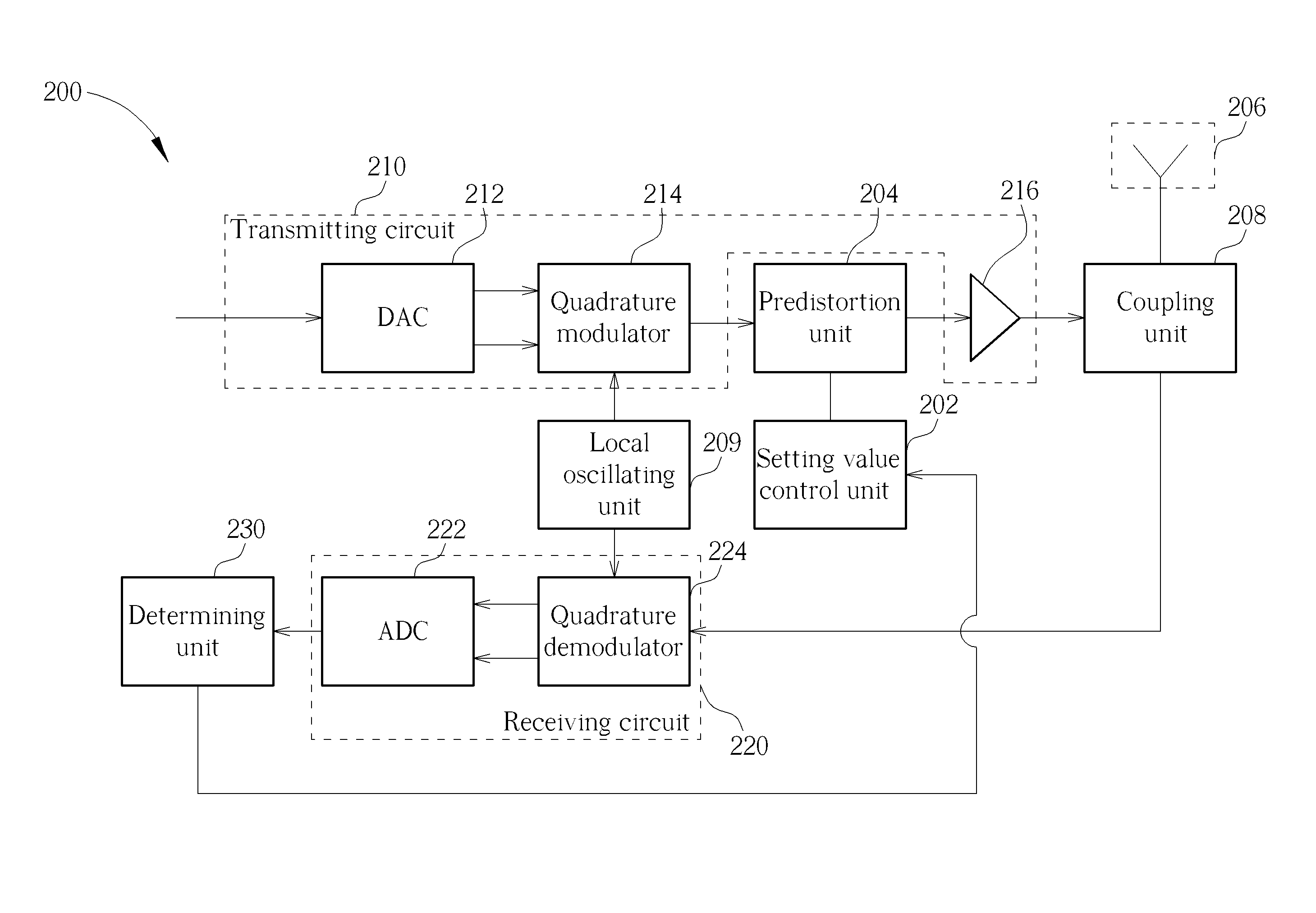
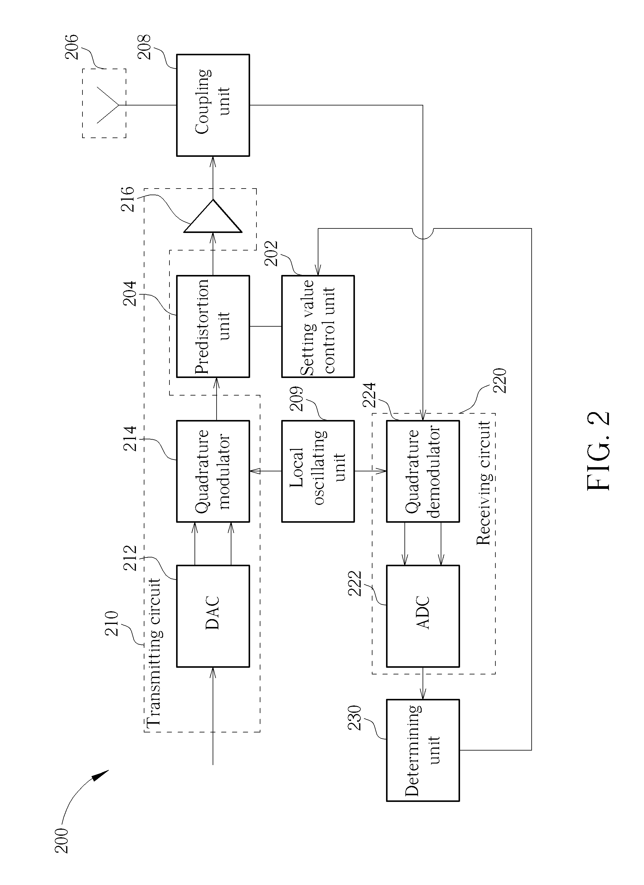
[0018]Please refer to FIG. 2. FIG. 2 shows a simplified block diagram of a transmitting device 200 according to the present invention. As shown in FIG. 2, the transmitting device 200 comprises: a setting value control unit 202, a predistortion unit 204, an antenna unit 206, a coupling unit 208, a local oscillating unit 209, a transmitting circuit 210, a receiving circuit 220, and a determining unit 230, wherein the transmitting circuit 210 comprises a DAC 212, a quadrature modulator 214, and a power amplifier 216, and the receiving circuit 220 comprises an ADC 222 and a quadrature demodulator 224. In addition, the quadrature modulator 214 comprises two multipliers (not shown), a ninety-degree phase shifter (not shown), and an adder (not shown). Please note that the operational details and configuration details related to the antenna unit 206, the coupling unit 208, the local oscillating unit 209, the DAC 212, the quadrature modulator 214, the ADC 222, the quadrature demodulator 224,...

second embodiment

[0021]Please refer to FIG. 4. FIG. 4 shows a simplified block diagram of a determining unit 230 in a transmitting device 200 according to the present invention. As shown in FIG. 4, the determining unit 230 comprises: a power measuring circuit 240, a multiplying circuit 250, and a determining circuit 260. The power measuring circuit 240 is utilized for measuring a power estimation value of each receiving signal of the plurality of receiving signals. The multiplying circuit 250 is coupled to the power measuring circuit 240, and utilized for multiplying the power estimation value of each receiving signal of the plurality of receiving signals with an inverse value of a transmitting power value (such as 1 / Tx shown in FIG. 4) corresponding to the receiving signal, to generate a plurality of power gain values respectively corresponding to the plurality of receiving signals. The determining circuit 260 is coupled to the multiplying circuit 250, and utilized for determining the plurality of ...

third embodiment

[0028]Please refer to FIG. 8. FIG. 8 is a flowchart illustrating a method of determining a target predistortion setting value employed for the transmitting device 200 in the present invention, which comprises the Steps 802˜822.

[0029]Briefly summarized, the present invention can predistort signals before a power amplifier in a transmitting device by a method of determining a target predistortion setting value (i.e. an optimal predistortion setting value) from a plurality of candidate predistortion setting values. In this way, signals outputted by the power amplifier in the transmitting device can be adjusted to an optimal state, so as to solve the distortion problem of the outputted signals of the power amplifier.


PUM


Abstract

The present invention provides a transmitting device and a method for determining a target predistortion setting value. The transmitting device comprises: a setting value control unit, a predistortion unit, a transmitting circuit, a receiving circuit, and a determining unit. The present invention can predistort signals before a power amplifier in a transmitting device by a method of determining a target predistortion setting value (i.e. an optimal predistortion setting value) from a plurality of candidate predistortion setting values. In this way, signals outputted by the power amplifier in the transmitting device can be adjusted to an optimal state, so as to solve the distortion problem of the outputted signals of the power amplifier.

Description

CROSS REFERENCE TO RELATED APPLICATIONS[0001]This application claims the priority of U.S. Provisional Application No. 61 / 184,831, filed on Jun. 7, 2009, which is included herein by reference in its entirety.BACKGROUND OF THE INVENTION[0002]1. Field of the Invention[0003]The present invention relates to a transmitting device, and more particularly, to a transmitting device capable of solving distortion problems of output signals of a power amplifier and a method capable of determining a target predistortion setting value (i.e. an optimal predistortion setting value) from a plurality of candidate predistortion setting values, so as to solve the above problem.[0004]2. Description of the Prior Art[0005]In a wireless communication system, a transmitting device generally has a power amplifier at an output terminal to amplify a signal which is going to be transmitted and output the amplified signal. However, the power amplifier has a worse linearity when a larger power is inputted, and thu...

Claims


Application Information

Patent Timeline
Patent Type & Authority Patents(United States)
IPC IPC(8): H04B1/38
CPCH03F1/3241H03F3/24
Inventor CHANG, YUAN-SHUO
Owner REALTEK SEMICON CORP
Why Eureka
Try Eureka