Lens scanning mode hyperspectral imaging system and rotor unmanned aerial vehicle

a scanning mode and hyperspectral imaging technology, applied in the field of laser scanning mode hyperspectral imaging system and rotor unmanned aerial vehicle, can solve problems such as image distortion, achieve the effects of solving the instability of the center of gravity, avoiding image distortion, and enlarging an application field

Active Publication Date: 2019-10-08
JIANGSU DUALIX SPECTRAL IMAGING TECH CO LTD
View PDF3 Cites 0 Cited by
  • Summary
  • Abstract
  • Description
  • Claims
  • Application Information

AI Technical Summary

Benefits of technology

[0026]1. the hyperspectral imaging system of the present invention provides relative motion between the target object and the imaging spectrometer by means of the lens scanning mode to achieve imaging, which solves the image distortion problem of conventional hyperspectral imaging system using a slit scanning mode or a scanning mode, and is suitable for the environment with the high altitude and the large scanning range;
[0027]2. the hyperspectral imaging system of the present invention overcomes the technical bias in the prior art that the imaging lens must be fixed, wherein in the environment with the high altitude and the large scanning range, a change of a field of view of an image caused by the imaging lens is very small within the scanning distance range of 10±2 mm, and position information of the target object is basically unchanged, which will not affect a final image quality;
[0028]3. the lens scanning mode of the present invention can also be applied to other non-hyperspectral imaging modes, and the information acquisition can also be performed; in this case, image information and spectral information are no longer acquired, but only the spectral information of the target is obtained, which is conducive to enlarging an application field;
[0029]4. by carrying the hyperspectral imaging system, the unmanned aerial vehicle can fly and stop at the designated area, and then the hyperspectral imaging system uses the lens scanning method for image acquisition, which solves instability of the center of gravity caused by adjusting a scanning range with movement of the unmanned aerial vehicle, so as to avoid image distortion;
[0030]5. according to the present invention, costs of a rotor unmanned aerial vehicle carrying platform are low, wherein the platform can be control by a wireless transmission and remote control module, and the image acquisition areas, the attitude of the rotor unmanned aerial vehicle and the captured image effects can be observed on the group; in addition, the unmanned aerial vehicle can also quickly complete shooting and stitching of a large area of the target image; meanwhile, the unmanned aerial vehicle provides relevant GPS positioning information, and together with ground indicators, shooting and stitching of an even larger area of the target image are able to be completed soon, so there is no need for real-time adjusting unmanned aerial vehicle flight attitude, speed, etc.
[0031]6. the present invention does not need very professional persons to operate, and only person able to control the flight attitude of the unmanned aerial vehicle is needed, wherein due to automation and modularization of image acquisition, test efficiency is greatly improved;

Problems solved by technology

In the conventional hyperspectral imaging system, in order to ensure that the lens field of view and the captured image field of view will not change, the imaging lens is fixed no matter with a slit scanning mode or a rotary mirror scanning mode, However, both of the scanning modes will lead to image distortion.

Method used


Image

  • Lens scanning mode hyperspectral imaging system and rotor unmanned aerial vehicle
  • Lens scanning mode hyperspectral imaging system and rotor unmanned aerial vehicle
  • Lens scanning mode hyperspectral imaging system and rotor unmanned aerial vehicle

Examples


embodiment 1

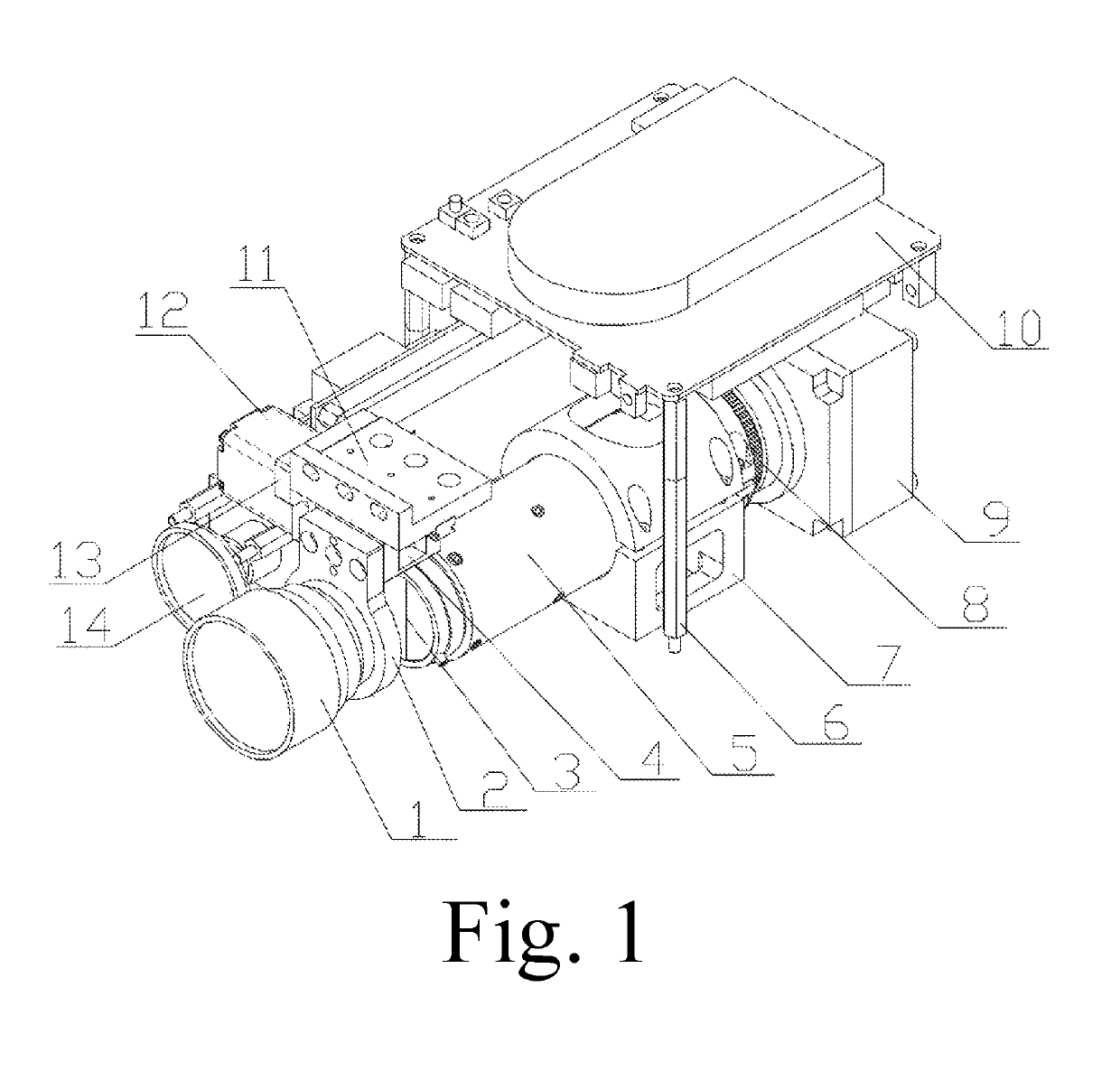
[0041]A lens scanning mode hyperspectral imaging system is provided, comprising: an imaging lens 1, an imaging spectrometer 5 and a surface array detector 9 arranged in sequence and coaxial to a main optic axis, wherein the imaging spectrometer 5 and the surface array detector 9 are connected and mounted to each other; wherein the lens scanning mode hyperspectral imaging system further comprises: a driving device for driving the imaging lens 1 to translate relative to a plane where a slit 3 of the imaging spectrometer 5 is; the imaging lens 1 forms a lens scanning mode during translating, and a scanning distance is 10±2 mm.

[0042]In the conventional hyperspectral imaging system, in order to ensure that the lens field of view and the captured image field of view will not change, the imaging lens 1 is fixed no matter with a slit scanning mode or a rotary mirror scanning mode, However, both of the scanning modes will lead to image distortion. Based on the fact that the imaging spectrome...

embodiment 2

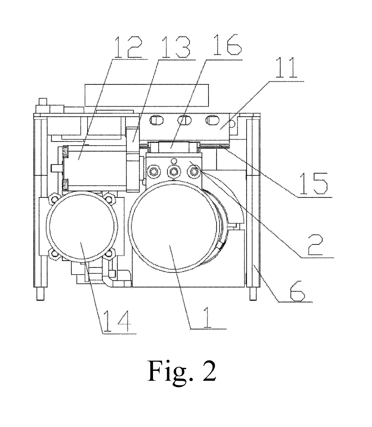
[0045]Based on the embodiment 1, the driving device comprises: a translation mechanism mounted to the imaging lens 1, and a scanning motor 12 for driving the translation mechanism. The translation mechanism is driven by the scanning motor 12, so as to drive the imaging lens 1 to scan. After scanning, the scanning motor 12 resets the translation mechanism.

embodiment 3

[0046]Based on the embodiment 2, the translation mechanism comprises: a fixing board 11 on a top of the translation mechanism, a sliding rail 15 fixedly connected to the fixing board 11, and a slider 16 movable along the sliding rail 15, wherein the slider 16 is connected to the imaging lens 1 through an imaging lens fixer 2. The imaging lens 1 is driven to scan by the sliding rail 15 and the slider 16, which provides a simple structure and convenient operation, and is conducive to lowering costs.


PUM


Abstract

A lens scanning mode hyperspectral imaging system and a rotor unmanned aerial vehicle include: an imaging lens, an imaging spectrometer and a surface array detector arranged in sequence and coaxial to a main optic axis, wherein the imaging spectrometer and the surface array detector are connected and mounted to each other; wherein the lens scanning mode hyperspectral imaging system further includes: a driving device for driving the imaging lens to translate relative to a plane where a slit of the imaging spectrometer is. The hyperspectral imaging system of the present invention overcomes the technical bias in the prior art that the imaging lens must be fixed, and the present invention provides relative motion between the target object and the imaging spectrometer by the lens scanning mode for imaging, which solves the image distortion problem of conventional hyperspectral imaging system using a slit scanning mode or a scanning mode.

Description

CROSS REFERENCE OF RELATED APPLICATION[0001]The present invention claims priority under 35 U.S.C. 119(a-d) to CN 201710468197.5, filed Jun. 20, 2017.BACKGROUND OF THE PRESENT INVENTIONField of Invention[0002]The present invention relates to a technical field of rotor unmanned aerial vehicle hyperspectral imaging, and more particularly to a lens scanning mode hyperspectral imaging system and a rotor unmanned aerial vehicle.Description of Related Arts[0003]Hyperspectral technology is a newly-developed interdisciplinary subject, which is based on technologies such as sensors and computers, and is relative to electromagnetic wave theory, spectroscopy and chroma, physical / geometric optics and other disciplines. Electromagnetic wave theory is the physical basis of remote sensing technology, wherein the interaction mechanism between electromagnetic wave and surface matter, and the transmission model of electromagnetic wave in different media and its receiving as well as analysis are the co...

Claims


Application Information

Patent Timeline
Patent Type & Authority Patents(United States)
IPC IPC(8): G01J3/06G01J3/28G01J3/02B64C39/02B64D47/08
CPCG01J3/06B64D47/08G01J3/2823G01J3/0208B64C39/024G01J2003/2826G01J2003/062B64C2201/123G01J2003/061B64U2101/30
Inventor CHEN, XINGHAILIU, YELINHUANG, ZHIHUIHUANG, YU
Owner JIANGSU DUALIX SPECTRAL IMAGING TECH CO LTD
Why Eureka
Try Eureka