Printing unit

a printing press and printing unit technology, applied in printing, rotary letterpress machines, lithographic machines, etc., can solve the problems of negative impact on printing quality, impair printing quality, and large print area, so as to improve printing quality and improve control quality of driv

Active Publication Date: 2013-04-16
MANROLAND WEB SYST
View PDF24 Cites 2 Cited by
  • Summary
  • Abstract
  • Description
  • Claims
  • Application Information

AI Technical Summary

Benefits of technology

[0008]It is therefore an object of the invention to improve the control quality of the drive in a printing unit of a printing press and, therefore, improve the printing quality. This and other objects and advantages in accordance with the invention are achieved by providing a printing unit the invention in which a flywheel mass is associated with at least one drive motor which drives the form cylinder or the transfer cylinder of the respective printing couple, where the flywheel mass is connected to the rotor of the respective drive motor to provide torsional rigidity.
[0009]In accordance with the invention, the flywheel mass is connected to the rotor of the respective drive motor in a rigid manner and, therefore, in a torsionally rigid manner. The mass moment of inertia of the drive motor is increased by this flywheel mass so that the natural frequency of the oscillating system comprising the drive motor and driven cylinders is also increased. As a result, the filter range of the filter of the drive controller of the respective drive motor is also raised. The drive controller of the drive motor can then better correct interference in a lower frequency range, i.e., in the range of the original natural frequency, so that a more stable control can be generally achieved. As a result, it becomes possible to prevent doubling in the print area to a great extent, and the printing quality can also be improved.

Problems solved by technology

When this oscillating system is excited by a frequency on the order of the natural frequency, vibrations develop which negatively impact the printing quality.
This is achieved in that the controller filters out, and therefore does not correct, interference in the load torque curve in the range of the natural frequency of the oscillating system.
However, since fluctuations in torque, which are not detected because of the filtering in the drive controller of the drive motor and can therefore not be corrected, can also act on the drive motor in the neighborhood of the natural frequency of the oscillating system, doubling can develop in the print area, which impairs printing quality.

Method used


Image

  • Printing unit
  • Printing unit
  • Printing unit

Examples


Embodiment Construction

[0015]The present invention is directed to a printing unit of a printing press, particularly a printing unit of a web press constructed as a periodical printing press. In alternative embodiments, the printing unit comprises a printing unit in a web press which is constructed as a newspaper printing press.

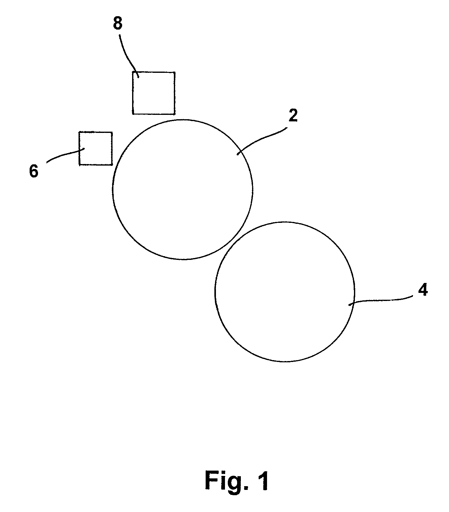
[0016]A printing unit of a web press has a plurality of printing couples. As schematically shown in FIG. 1, each printing couple has a form cylinder 2, also known as a plate cylinder, a transfer cylinder 4, also known as a blanket cylinder, which rolls upon the form cylinder 2, an inking unit 6, and preferably a dampening unit 8+.

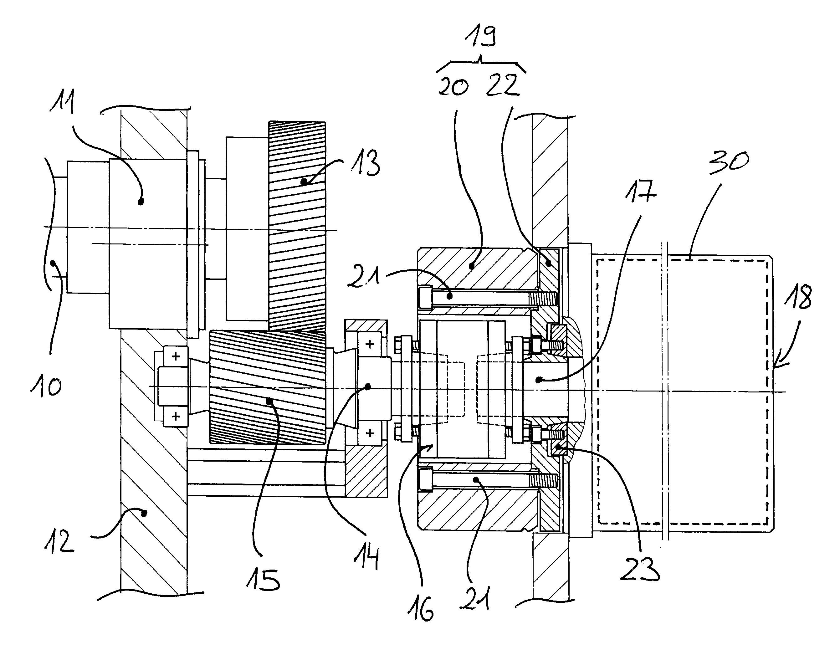
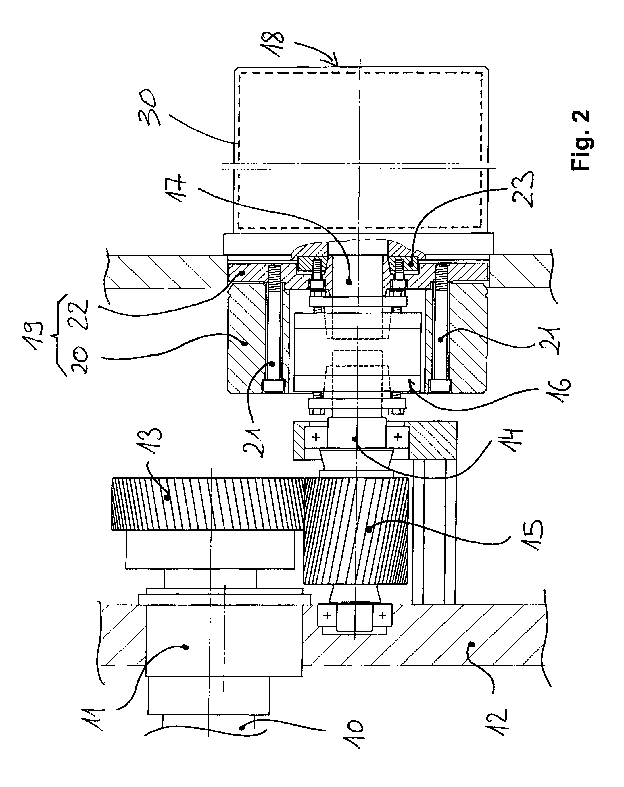
[0017]A separate drive motor is preferably associated with each printing couple in a printing unit of the type mentioned above, and drives either the form cylinder of the respective printing couple or the transfer cylinder of the respective printing couple. When the drive motor drives the transfer cylinder of the respective printing couple, the form cylinde...


PUM


Abstract

A printing unit of a printing press, such as a web press constructed as a periodical printing press, having at least one printing couple, wherein the printing couple or each printing couple comprises a form cylinder, a transfer cylinder, an inking unit, and preferably a dampening unit. A drive motor is associated with at least one printing couple, and drives the form cylinder or the transfer cylinder of a respective printing couple. In accordance with the invention, a flywheel mass is associated with at least one drive motor which drives the form cylinder or the transfer cylinder of the respective printing couple, where the flywheel mass is connected to the rotor of the respective drive motor in a torsionally rigid manner.

Description

BACKGROUND OF THE INVENTION[0001]1. Field of the Invention[0002]The invention is directed to a printing unit of a printing press and, more particularly, to a web press constructed as a periodical printing press.[0003]2. Description of the Related Art[0004]A printing unit of a web press constructed as a periodical printing press typically has two printing couples, where each printing couple comprises a transfer cylinder, a form cylinder, an inking unit and a dampening unit. The transfer cylinders are also called blanket cylinders, and the form cylinders are also known as plate cylinders. The transfer cylinders of the printing couples in a printing unit of this kind roll upon one another while forming a printing nip through which printing stock to be imprinted in the printing unit is conveyed in horizontal direction.[0005]It known to provide each printing couple in a conventional printing unit with a separate drive motor that drives either the form cylinder or the transfer cylinder of...

Claims


Application Information

Patent Timeline
Patent Type & Authority Patents(United States)
IPC IPC(8): B41F5/00
CPCB41F13/0008B41F13/008B41F13/085
Inventor SCHAFER, ANDRESTEGER, FRIEDRICHWAGNER, FRANK
Owner MANROLAND WEB SYST
Why Eureka
Try Eureka