Surgical suturing latch

a suture latch and latch technology, applied in the field of surgical suturing latches, can solve the problems of difficult suture needle manipulation, large number of suture stitches, and difficulty in placing suture needles, and achieve the effect of reducing the difficulty of manipulating suture needles and reducing the difficulty of placing suture stitches

Active Publication Date: 2013-04-16
BOSS INSTR
View PDF47 Cites 791 Cited by
  • Summary
  • Abstract
  • Description
  • Claims
  • Application Information

AI Technical Summary

Benefits of technology

[0010]Embodiments of the present invention provide improved suturing systems and methods that maintain some or all of the advantages of standard open and / or minimally invasive suturing techniques while providing enhanced speed, ease of use, convenience, reduced disease transmission risk, and ease of cleaning and sterilization. Exemplary suturing systems of the present invention will generally include a cartridge and a drive unit. The cartridge has a cartridge body, a plurality of needle grasping jaws, and a cartridge interface. The drive unit has a drive unit body, a linkage, and a drive unit interface. The drive unit interface and / or the cartridge interface will often include a latch that can hold the cartridge interface in engagement with the drive unit interface, and a released position for releasing the cartridge from the drive unit. A latch input is coupled to the latch so that a movement of the input moves the latch to the released position. The interfaces can be configured so that removal of the cartridge from the drive unit involves two opposed motions relative to the drive unit, such as pressing the input along a first direction while simultaneously pulling the cartridge away from the drive unit in a second direction substantially opposed to the first direction. Alternative cartridge embodiments may be removed by simultaneously pressing opposed inputs on the sides of the cartridge toward each other while pulling the cartridge away from the drive unit, or the like. Preferably, the cartridge interface or the drive unit interface includes a channel and the other includes a shaft which is fittingly receivable in the channel. The input may be mounted to the shaft so that the input is accessible beyond the channel of the cartridge body.
[0011]In a first aspect, the invention provides a suturing system for use with a needle. The suturing system comprises a cartridge and a drive unit. The cartridge has a cartridge body, a plurality of jaws, and a cartridge interface. The drive unit has a drive unit body, a linkage, and a drive unit interface. The cartridge interface is removably mountable to the drive unit interface. Cycling of the linkage effects alternating grasping of the needle by the jaws when the drive unit interface engages the cartridge interface and the needle is positioned for use. The drive unit interface or the cartridge interface includes a latch. The latch has at least two positions: a latched position maintaining the cartridge interface in engagement with the drive unit interface, and a released position releasing the cartridge from the drive unit. A latch input is coupled to the latch so that two opposed motions (each comprising a motion relative to the drive unit body) effect movement of the latch to the released position and removal of the cartridge from the drive unit.
[0014]In many embodiments, the latch is included in an interface assembly that is detachably mounted to the drive unit body. This facilitates sterilization and / or replacement of the interface assembly independently of at least a portion of the linkage.
[0019]The latch may be included in an interface assembly that is detachably mounted to the drive unit body. Having a detachably mounted interface assembly facilitates sterilization and / or replacement of the interface assembly independently of at least a portion of the linkage.
[0020]In another aspect, embodiments of the invention may provide a suturing cartridge for use with a needle in a suturing system, the suturing system includes a drive unit having a linkage, a drive unit interface including a latch, and a shaft assembly with an input. The cartridge comprises a cartridge body, a plurality of jaws, and a cartridge interface. The plurality of jaws is supported by the cartridge body so that cycling of the linkage effects alternating grasping of the needle by the jaws when the cartridge is mounted to the drive unit and the needle is positioned for use. The cartridge interface includes a channel and a latch receiving surface. The channel fittingly receives the shaft assembly along a mounting orientation. The latch receiving surface is engageable by the latch so as to restrain the cartridge interface in engagement with the drive unit interface, and so that actuation of the input is transmitted through the channel so as to release the cartridge from the drive unit.
[0021]Movement of the cartridge along the mounting orientation can effect movement of the latching surface to the latched position.

Problems solved by technology

In particular, placing a large number of suture stitches can be tiring and quite time-consuming.
Manipulation of a suture needle can be difficult even in open surgery due to the limited space that is often available around the target tissues.
The challenges of manipulating suture needles may be even greater in minimally invasive surgical procedures, where the needles are often manipulated using long-handled tools extending through a small aperture, typically while viewing the procedure on a display which is offset from the surgical site.
Tying knots with a desired amount of tension and the like may call for intricate and precise manipulation of the suture, further complicating and delaying open and minimally-invasive surgeries.
Additionally, repeated needle manipulations associated with stitches and knot tying may increase the needle stick risk—an inadvertent needle puncture to the surgeon or other member of the surgical team.
Such needle sticks can increase the risk of infection to the surgical staff and patient.
At least some of these proposals may seek to rely on specialized and / or proprietary suturing needle systems, which could increase costs and preclude their wide acceptance, especially in third world countries.
Unfortunately, many proposals for modifying existing suturing techniques may also decrease the surgeon's control over the placement of the suture, such as by relying on an automated or indirect mechanical movement of a device to drive a suture needle into and / or through tissues.

Method used


Image

  • Surgical suturing latch
  • Surgical suturing latch
  • Surgical suturing latch

Examples


Embodiment Construction

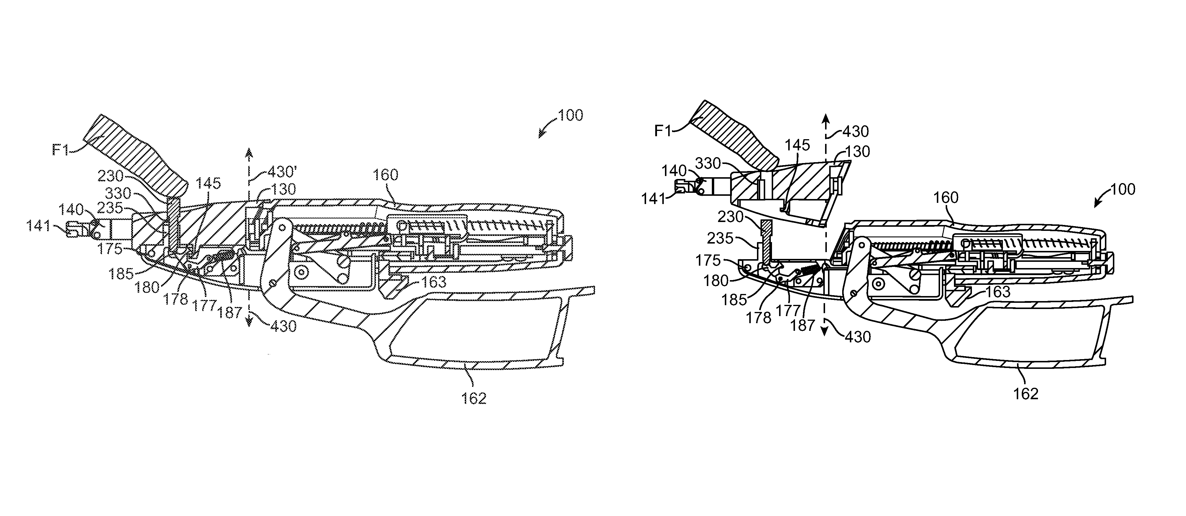
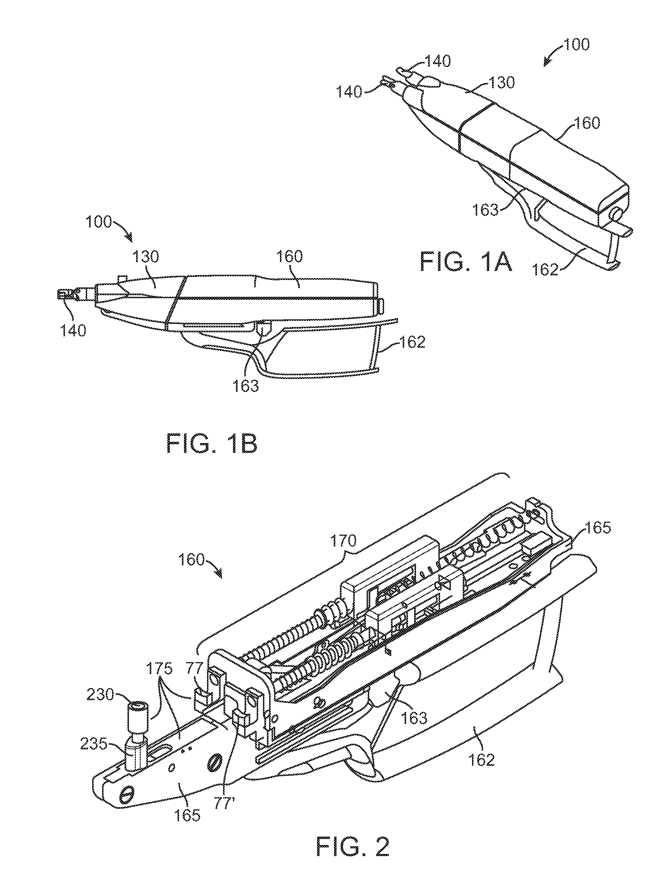
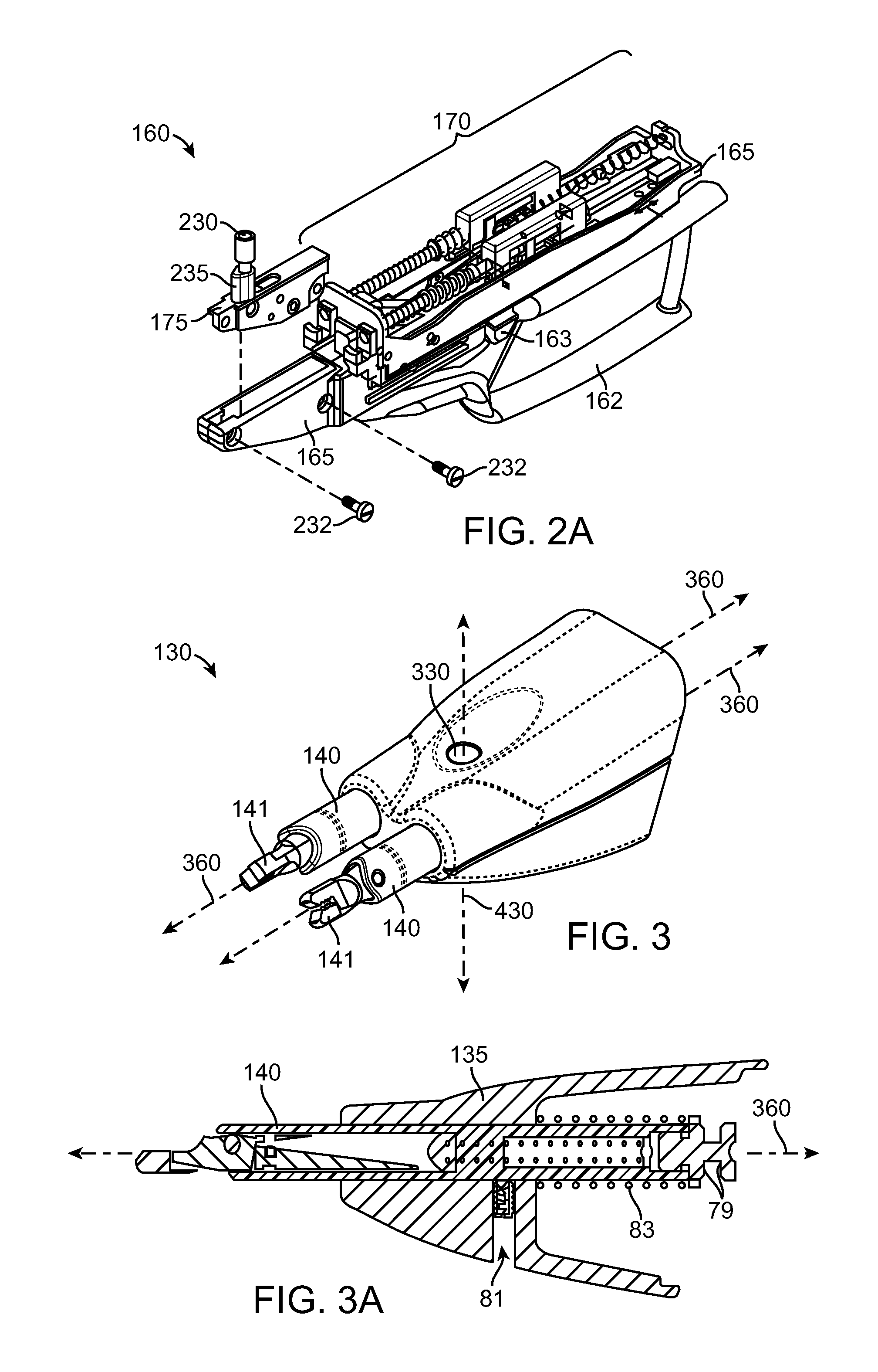
[0039]The present invention is generally directed to improved medical suturing devices, systems, and methods. Exemplary embodiments of the invention provide improved suturing devices and methods for suturing tissues that can significantly increase the speed and ease of suturing, particularly when suturing of long incisions or where large numbers of stitches are to be deployed, and that have easily removable parts for ease of cleaning and sterilization.

[0040]The invention should find a wide variety of applications for stitching anatomical tissues in both humans and animals. Along with endoscopic operations (for example, in laparoscopy) these structures and methods may find use in other areas of surgery where tissues are to be stitched, providing particular advantages for stitching of large incisions by increasing the ease and speed with which each individual stitch may be placed, as well as facilitating and expediting the formation of knots in the suture. The suturing devices and ass...


PUM


Abstract

Suturing systems may comprise a cartridge and a drive unit which are detachable from each other. The cartridge often has a cartridge body, a plurality of jaws, and a cartridge interface. The drive unit has a drive unit body, a linkage, and a drive unit interface which will typically include a latch. A latch input is coupled to the latch so that a movement of the input moves the latch to the released position. The cartridge interface or the drive unit interface includes a channel while the other includes a shaft which is fittingly receivable in the channel. Opposed motions of the input and cartridge during cartridge removal avoid inadvertent detachment during use.

Description

CROSS REFERENCE TO RELATED APPLICATION DATA[0001]The present application claims the benefit under 35 USC 119(e) of U.S. Provisional Application No. 61 / 145,390 filed Jan. 16, 2009; the full disclosure of which is incorporated herein by reference in its entirety.BACKGROUND OF THE INVENTION[0002]The present invention generally relates to medical devices, systems, and methods. In specific embodiments, the invention provides devices, systems, and methods for suturing tissues in open surgery, minimally invasive surgical procedures, and the like. In particular, many embodiments of the invention provide suturing systems and devices which have parts that are removable from each other.[0003]Although many aspects of surgery have changed radically over the last several decades, some surgical techniques have remained remarkably constant. For example, as was true fifty years ago, suturing remains a common technique for approximation of tissues, ligation of tissues, affixing tissues together, and ...

Claims


Application Information

Patent Timeline
Patent Type & Authority Patents(United States)
IPC IPC(8): A61B17/04
CPCA61B17/0491A61B17/0482A61B17/0469A61B2017/00477A61B2017/00464A61B2017/00473A61B17/28A61B17/062A61B17/29A61B2017/0046
Inventor LABY, KEITH PHILLIPMOORE, PATRICIA A.
Owner BOSS INSTR
Why Eureka
Try Eureka