Systems, methods and devices for correcting spinal deformities

a spinal deformity and spinal nerve technology, applied in the field of spinal nerve deformity correction, can solve the problems of increased blood loss, increased risk of vertebral body fusion, and significant invasive surgery, and achieves the effects of reducing the risk of fusion

Inactive Publication Date: 2013-04-16
REDUCTION TECH
View PDF63 Cites 36 Cited by
  • Summary
  • Abstract
  • Description
  • Claims
  • Application Information

AI Technical Summary

Problems solved by technology

Spinal fusion can oftentimes largely correct a spinal deformity but can also result in complications, such as when the patient advances into adult life.
However, because the implantation procedure is so invasive, it can lead to increased blood loss, generation of scar tissue and may induce the risk that the vertebral bodies will still fuse through reaction of the body itself, i.e., auto-fusion.
The '831 patent teaches use of a rigid dual-rod arrangement with fixed and mobile brackets that are anchored to the transverse process and, thus, require significant invasive surgery and risk consequent fusion.
However, this configuration allows the curved rod to rotate out of alignment with the spinal column and, consequently, shifts the direction in which the corrective force is intended to be applied.
Use of the ball-and-socket joint with a fixed bracket further causes the point of articulation to be undesirably offset from the rod itself.
Anchoring to the transverse process is also employed, which, again, is a major drawback in performing the techniques suggested in the '175 patent.
Further, this device theoretically overcomes the deformity with constant force applied by pre-curved correction members, but this does not allow for resultant changes in the deformity or tissue relaxation.
Because of the use of these pre-curved rods, the technique suggested in the '175 patent may actually result in a final deformity completely opposite to the original deformity due to tissue growth and relaxation.
Furthermore, this device risks alteration of the natural biomechanics of the spine by fixing the distance between points of attachment.
However, the mechanical assembly suggested in the '582 patent is appended to an area on each vertebrae between the spinal process and transverse process, which, again, results in significant invasive surgery, (as discussed earlier) and can result in fusion of vertebral bodies in the to-be corrected region.

Method used


Image

  • Systems, methods and devices for correcting spinal deformities
  • Systems, methods and devices for correcting spinal deformities
  • Systems, methods and devices for correcting spinal deformities

Examples


Embodiment Construction

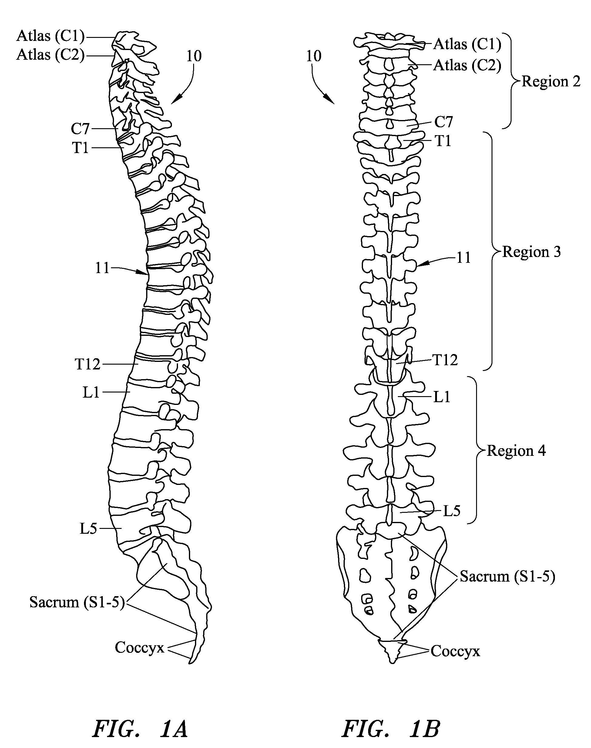
[0078]To facilitate the description of the systems, devices and methods provided herein, a discussion will first be set forth of basic healthy spinal anatomy and deformities that can occur thereto. FIG. 1A is a lateral view of a normal human spinal column 10. Spinal column 10 is divided into three principal regions. The top, or superior, region 2 includes seven vertebral bodies 11 and is referred to as the “cervical” region of the spine. These seven bodies are consecutively labeled C1-C7. The intermediate region 3 includes twelve vertebral bodies 11 and is referred to as the “thoracic” region of the spine. These twelve bodies are consecutively labeled T1-T12. The bottom, or inferior, region 4 includes five vertebral bodies 11 and is referred to as the “lumbar” region. These five bodies are consecutively labeled L1-L5.

[0079]In a general sense, a typical healthy spinal column 10 has curvature in the sagittal plane (depicted in FIG. 1A) but not in the coronal plane (depicted in the pos...


PUM


Abstract

Provided herein are systems, devices and methods for the correction of spinal deformities with the use one or more implantable rods configured to apply a corrective force to the spine. Methods of minimally invasive implantation of a corrective system are provided, such as where the corrective system is attached only to the spinous process of one or more vertebral bodies. Various corrective systems as well as components thereof are also provided, such as those that allow limited movement with respect to the spinal column.

Description

CROSS-REFERENCE TO RELATED APPLICATIONS[0001]This application claims the benefit of U.S. Provisional Application Ser. No. 61 / 185,079, filed Jun. 8, 2009, which is incorporated herein by reference.FIELD OF THE INVENTIONS[0002]The subject matter described herein relates generally to the correction of spinal deformities.BACKGROUND OF THE INVENTIONS[0003]Scoliosis, a disease that deforms the spine, affects more girls than boys and manifests itself during the teen years when significant growth is experienced. Scoliosis generally combines a horizontal torsion and flexion in a frontal plane and develops in three spatial dimensions. As noted, the disease generally begins with the growth phase, as it is hypothesized that this is probably due to the rotation of one or two vertebral bodies.[0004]Sufferers of scoliosis are generally treated initially with a rigid corset-like orthopedic brace. If this treatment proves unsuccessful, another treatment option can include spinal fusion through invas...

Claims


Application Information

Patent Timeline
Patent Type & Authority Patents(United States)
IPC IPC(8): A61B17/70
CPCA61B17/7004A61B17/701A61B17/7019A61B17/7025A61B17/7031A61B17/7049A61B17/7068A61B17/707A61B17/70A61B17/7028A61B17/809A61B2017/00867
Inventor THOMPSON, MATTHEWCHEE, HIRAMGINN, RICHARDGITTINGS, DARINSEPETKA, IVANWHITE, DAVID
Owner REDUCTION TECH
Why Eureka
Try Eureka