Estimating objects proper motion using optical flow, kinematics and depth information

a technology of depth information and object motion, applied in image data processing, instruments, character and pattern recognition, etc., can solve the problems of not being able to achieve the effect of autonomously acting robots in dynamic scenes, not being able to simplify the assumption about the environment, and not being able to cope properly

Inactive Publication Date: 2013-04-16
HONDA RES INST EUROPE
View PDF9 Cites 8 Cited by
  • Summary
  • Abstract
  • Description
  • Claims
  • Application Information

AI Technical Summary

Problems solved by technology

While this procedure may be suitable for the car domain, no such simplifying assumption about the environment is appropriate for autonomously acting robots in dynamic scenes.
However, all the results of the provided approaches are not very promising, possibly due to a missing integration of depth information.
Nevertheless, this approach can not cope properly with objects having a distance different from objects in the training-phase: The difference in distance results in an optical flow (OF) deviating from the learned one.
Unfortunately, the noisy data from odometry forces the authors to manually measure the distance passed by the robot, preventing the system from running in real time.
None of the presented methods precomputes a movement of the camera and searches for movement relative to it.
The higher range of acquired motion does not only increase the computational time but also corrupts optical flow (OF)-estimations by producing increased ambiguities.
However, apparently no procedure was presented which is able to handle the noisy character of depth, optical flow (OF) and the fierce effects of camera-movement induced by a legged robot, combining them to make reliable estimations of object proper motion (OPM).
However, this assumption about the depth is not applicable in all situations in which an accurate estimate of the proper motion of an object is desired.

Method used


Image

  • Estimating objects proper motion using optical flow, kinematics and depth information
  • Estimating objects proper motion using optical flow, kinematics and depth information
  • Estimating objects proper motion using optical flow, kinematics and depth information

Examples


Embodiment Construction

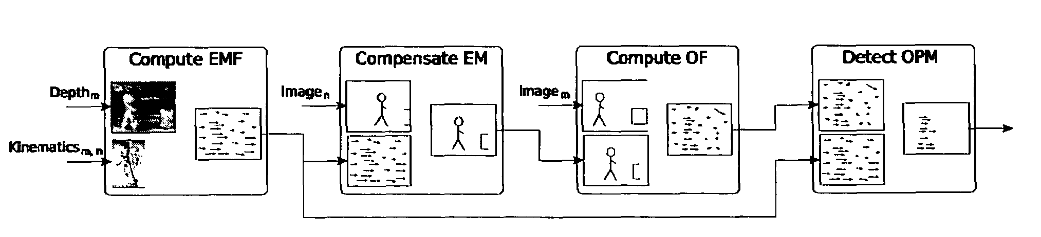
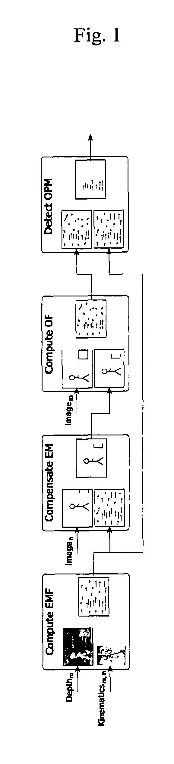
[0025]FIG. 1 shows an overview of a system according to the embodiments of the present invention:

[0026]In a first step the forward kinematics are used to compute the movement of the camera occurring in the time-interval from m to n=m+1. Combining this with the depth information from binocular disparity, one may estimate where a static point in the image at time m moved due to ego-motion (EM) and obtain the ego-motion-flow (EMF). Hence, by knowing where a point in the image at time n originated from, the ego-motion (EM)-effect may be compensated by moving the point back to its original position in a second step, resulting in an image freed from EM-effects. Afterwards this image may be used for a calculation of the optical flow (OF) measured relative to the ego-motion-flow (EMF). This step-by-step movement estimation allows the reduction of the optical flow's (OFs) search-range which does not only reduce computational time but also decreases possible ambiguities in the optical flow (O...


PUM


Abstract

The invention relates to a method for detecting the proper motion of an real-world object, comprising the steps of acquiring, by an image capturing device (ICD), a first image (I1) of the object at a first point in time (t1) and a second image (I2) at a second point in time (t2); obtaining a third (hypothetical) image (I3), based on an estimated effect of the motion of the image capturing device (ICD) itself (EMF) between the first and the second point in time (t1, t2), wherein the effect of the motion of the image capturing device (ICD) itself is estimated based on the forward kinematics of the image capturing device; determining an optical flow (OF) between the second image (I2) and the third image (I3); and evaluating the optical flow (OF) by incorporating uncertainties of the optical flow (OF) and the ego-motion-flow (EMF) in order to determine the proper motion of the object.

Description

[0001]The present invention relates to a method and a corresponding device for estimating the proper motion of an object (Object Proper Motion or OPM), using optical flow and kinematics and depth information, which is applicable in controlling autonomous mobile vehicles, such as robots or cars.TECHNICAL BACKGROUND[0002]The ability to visually perceive motion is believed to be highly beneficial for surviving in a dynamic environment. So it is not surprising to see that movement is one of the most important cues to attract visual attention. Interestingly, most mammals are able to perceive visual motion even if they are moving themselves—either by rotating the head, the eyes, moving the whole body or even while they are running. The gathered information is then used for controlling the own movement or for tracking moving objects by keeping them centred in the fovea.[0003]In general, a robot's autonomous movement causes the camera to undergo translational and rotational movements in 3D ...

Claims


Application Information

Patent Timeline
Patent Type & Authority Patents(United States)
IPC IPC(8): G06K9/00
CPCG06T7/2066G06T7/269
Inventor EGGERT, JULIANREBHAN, SVENSCHMUDDERICH, JENSWILLERT, VOLKER
Owner HONDA RES INST EUROPE
Why Eureka
Try Eureka