
Monitoring the water tables in multi-level ground water sampling systems

a water table monitoring and multi-level technology, applied in the field of pore fluid sampling and water table fluctuation history measurement, can solve the problems of a single-level sampling system in a single borehole that cannot allow such a simple measurement of the formation head, damage to other functioning transducers, and spread of ground water contamination, so as to avoid the hazards of transducers

Active Publication Date: 2013-04-23
KELLER CARL E
View PDF26 Cites 19 Cited by
  • Summary
  • Abstract
  • Description
  • Claims
  • Application Information

AI Technical Summary

Benefits of technology

[0007]There is disclosed hereby a method and associated apparatus for measuring the water level history at many levels in the formation surrounding a borehole. In the presently disclosed method and apparatus, however, all the pressure transducers are located at or above the Earth's surface where they are readily accessible. This change to conventional practice allows easy replacement of the transducers, or their reuse at other wells. The method also avoids the hazards to the transducers associated with emplacing transducers deep in the borehole during the multi-level system installation or removal.
[0008]Accordingly, there is provided a method and apparatus for measuring the water level history at many levels in a borehole in a subsurface geologic formation, with all of the pressure transducers located readily accessible near the surface. This improvement allows easy replacement of the transducers or their reuse at other wells. The method and apparatus disclosed hereby also avoids the hazards to the transducers associated with transducer emplacement deep in the borehole, during the multi-level system emplacement or during removal of the system. According to the invention, the transducers are connected to the sampling system by air-filled tubes. Changes in the air pressure in the tubes, and an associated air equation of state, are used with an algorithm to allow the water level changes deep in the formation to be accurately monitored. The present water level measurement method and apparatus, equipped with the air-coupled transducers, also may be conveniently calibrated, as desired, by manually measuring the water level for each water sampling elevation in the applicant's previously known “Water FLUTe” system. The present invention has a substantial beneficial effect on the cost, and therefore the overall utility, of known multi-level systems developed by the applicant. For a ten port system, this invention can reduce the long term cost of the multi-level sampling system by one half.

Problems solved by technology

Flexible borehole liners are installed by the eversion process to seal a borehole against flow into or out of the borehole, which flow can cause the spread of ground water contamination.
A multi-level sampling system in a single borehole does not allow such a simple measurement of the formation head at different levels in the formation.
However, if one (or more) transducer should fail, the entire multi-level system must be removed from the borehole to access and replace the failed transducers.
This removal, besides causing delay and expense, can result in damage to other functioning transducers, as well as to the flexible liner sampling system.
Certainly the multi-level water sampling system has been improved beyond the teachings of applicant's U.S. Pat. No. 5,176,207, or of applicant's co-pending U.S. patent application Ser. No. 12 / 001,801 entitled “Pore Fluid Sampling System with Diffusion Barrier.” The cost of removal and repair of failed transducers in known systems, however, can be a major expense of the design.
Also, the dedication of the transducers to the system is a very expensive feature of the system, and the transducers are not available for reuse in other applications.

Method used


Image

  • Monitoring the water tables in multi-level ground water sampling systems
  • Monitoring the water tables in multi-level ground water sampling systems
  • Monitoring the water tables in multi-level ground water sampling systems

Examples


Embodiment Construction

Best Mode for Practicing the Invention

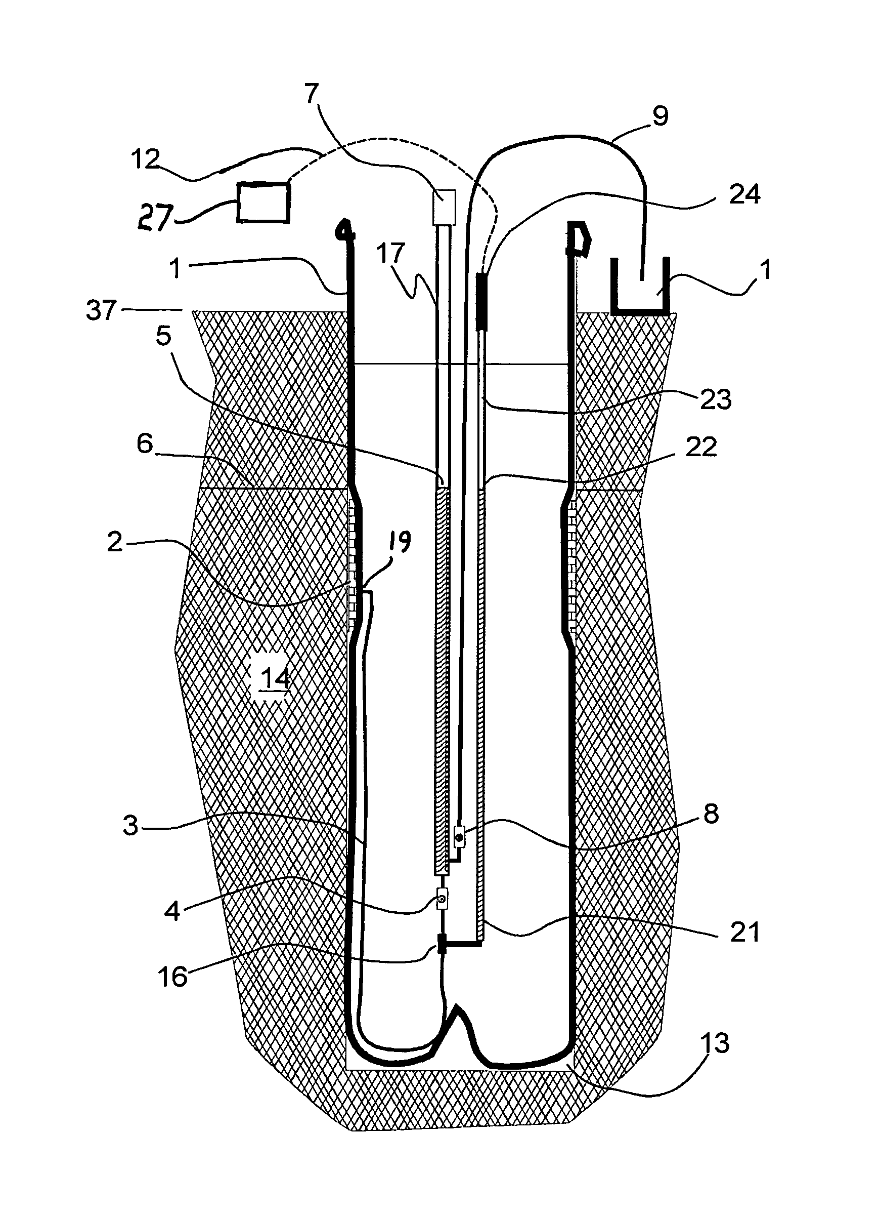
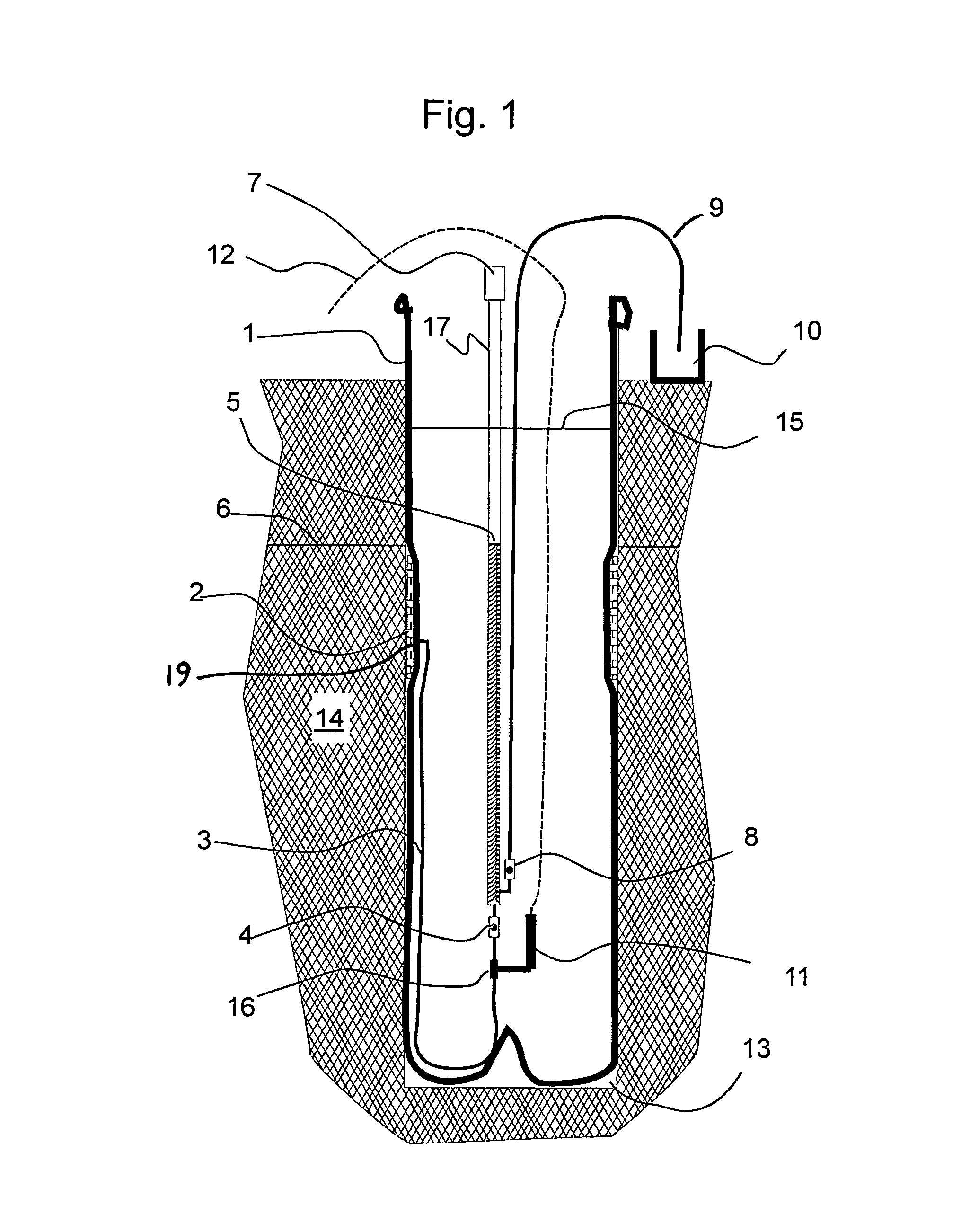
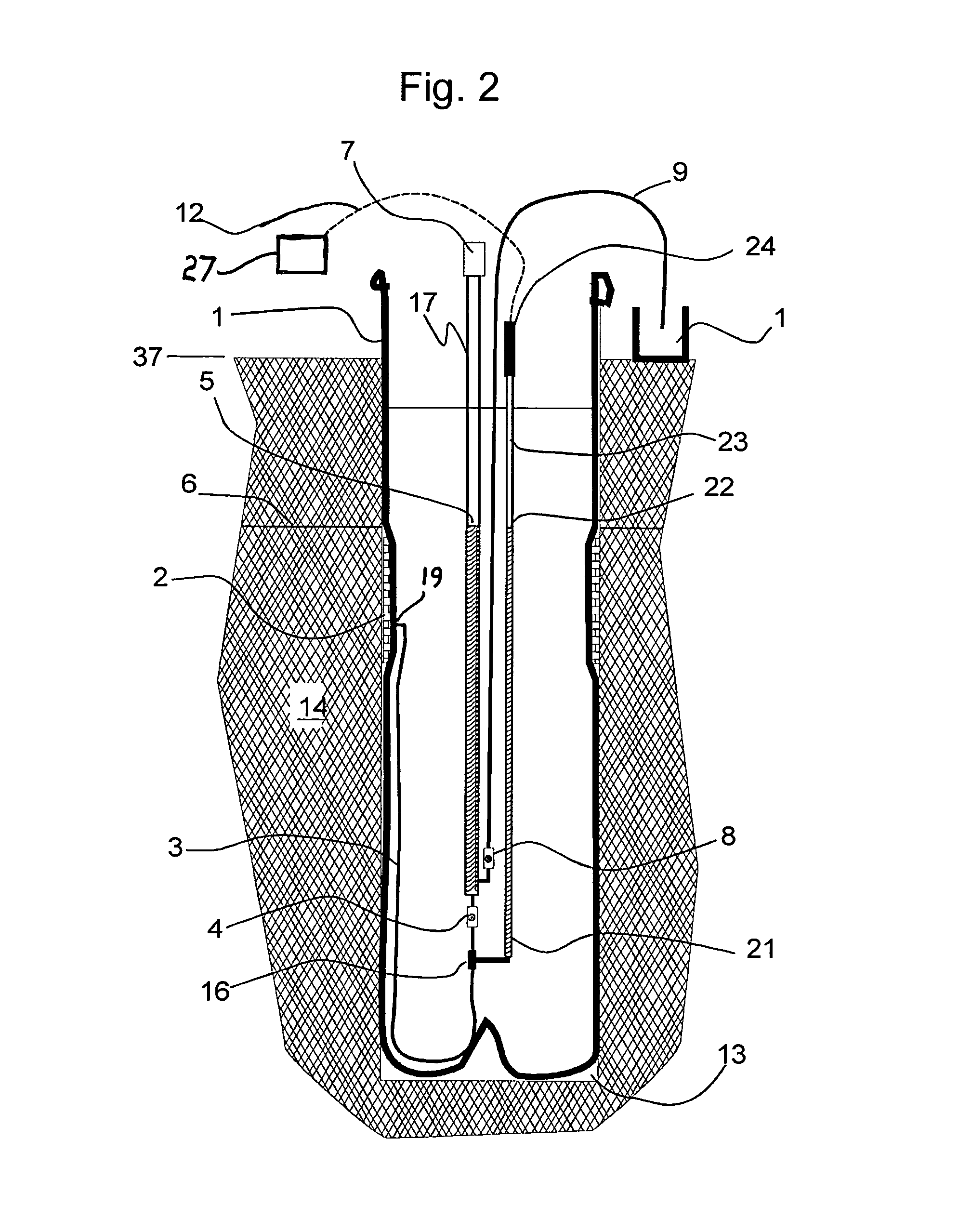
[0020]Flexible liners in boreholes have been designed by the applicant as shown in FIG. 1 for the purpose of extracting from the borehole a ground water sample by gas displacement of the water in the tubing. Only a single port is shown in FIG. 1 for clarity of illustration; the entire tubing system seen in FIG. 1 is duplicated for additional sampling elevations located on and within the same liner.

[0021]The sampling and monitoring system usually is emplaced into the borehole by an eversion process known in the art. The continuous impermeable liner 1 is installed by eversion into a borehole 13 in the geologic formation 14 as described generally in, for example, U.S. Pat. No. 5,176,207. The liner 1 is pressurized by the liner's interior water level 15 being above the formation water level 6 in the adjacent geologic formation 14. Once emplaced, the sample tubing of the system fills with water from the formation 14. Ambient water in the formation 14...


PUM


Abstract

An apparatus and method for monitoring the water tables in boreholes, such as boreholes used as sampling wells for sampling contaminants in ground water. Fluctuations in one or more ground water levels can be monitored and recorded using transducers, and the changes in the water levels evaluated and considered, particularly in the context of sampling for contaminants where subsurface pollution remediation is contemplated or ongoing. The changes in ground water levels can be tracked in time and correlated, as desired, with the water sampling regime. The transducers used for monitoring pressure changes attributable to water table changes are located advantageously above the surface of the ground, where they are accessible for re-use, replacement, or repair. Apparatus and method for providing an air-coupling between the transducers and subsurface sampling points is disclosed.

Description

CROSS-REFERENCE TO RELATED APPLICATIONS[0001]This application claims the benefit of the filing of U.S. Provisional Patent Application Ser. No. 61 / 268,870, titled “Monitoring the Water Tables in Multi-level Ground Water Sampling Systems,” filed on 17 Jun. 2010, and the specification thereof is incorporated herein by reference.FIELD OF THE INVENTION[0002]This invention relates generally to borehole liners, and more particularly to pore fluid sampling and other similar uses for everting flexible borehole liners, and specifically to the measurement of water table fluctuation histories at many elevations in a borehole.BACKGROUND OF THE INVENTION[0003]Flexible borehole liners are installed by the eversion process to seal a borehole against flow into or out of the borehole, which flow can cause the spread of ground water contamination. The installation method as commonly practiced propagates an everting borehole liner into the hole by adding water to the interior of the everting liner, whi...

Claims


Application Information

Patent Timeline
Patent Type & Authority Patents(United States)
IPC IPC(8): E21B49/08
CPCE21B43/103E21B47/042E21B47/047
Inventor KELLER, CARL E.
Owner KELLER CARL E
Learn More