Eureka AIR delivers breakthrough ideas for toughest innovation challenges, trusted by R&D personnel around the world.

Retinal instrument

a technology of retinal instruments and epiretinal membranes, applied in the field of surgical instruments, can solve the problems of underlying vessels, significant bleeding, and difficulty in manual peeling of epiretinal membranes from the retina, and achieve the effect of reducing the difficulty of manual peeling, and reducing the difficulty of surgical removal

Active Publication Date: 2013-04-23
UNIV OF TENNESSEE RES FOUND +1
View PDF9 Cites 6 Cited by
  • Summary
  • Abstract
  • Description
  • Claims
  • Application Information

AI Technical Summary

Benefits of technology

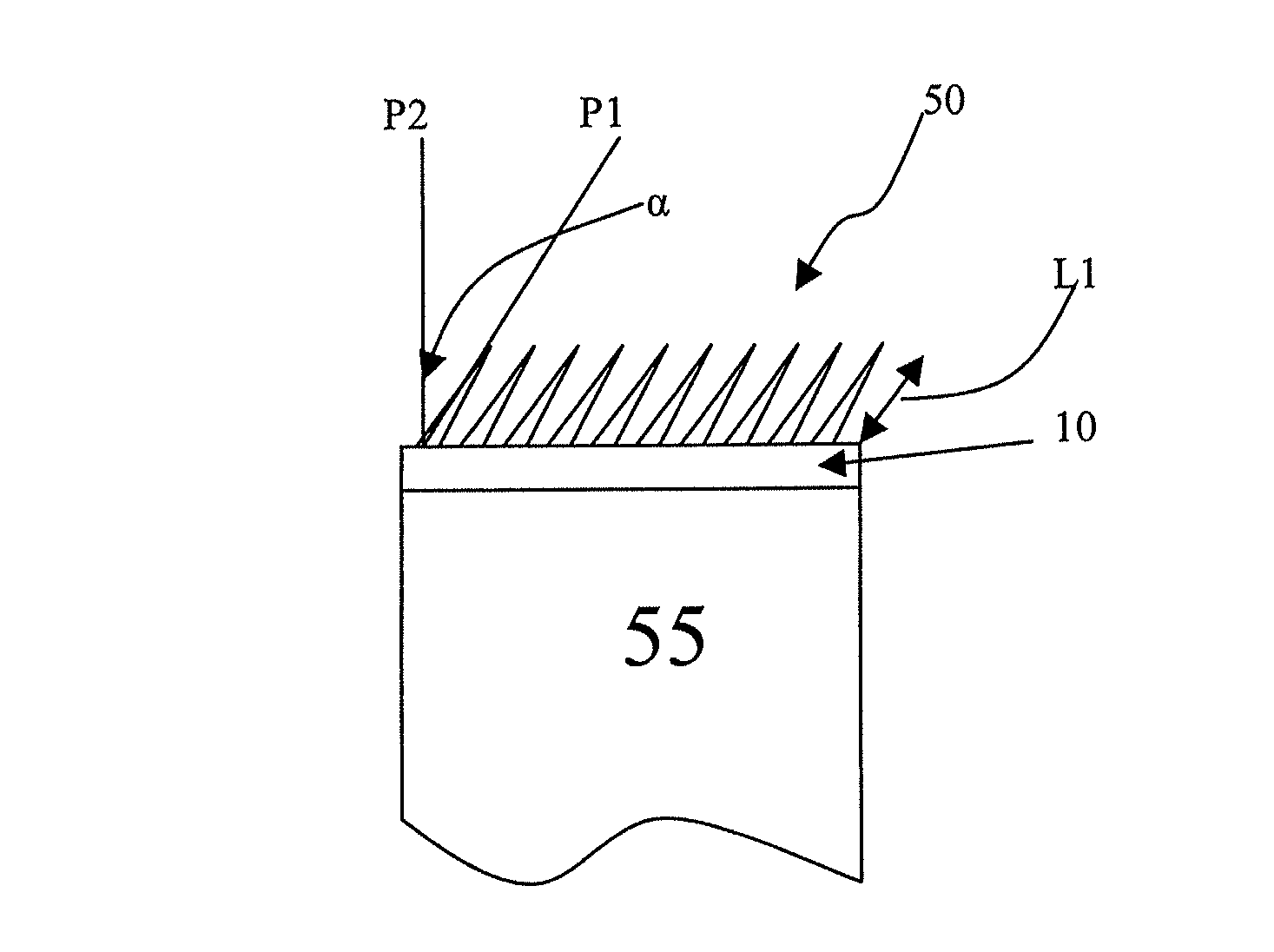
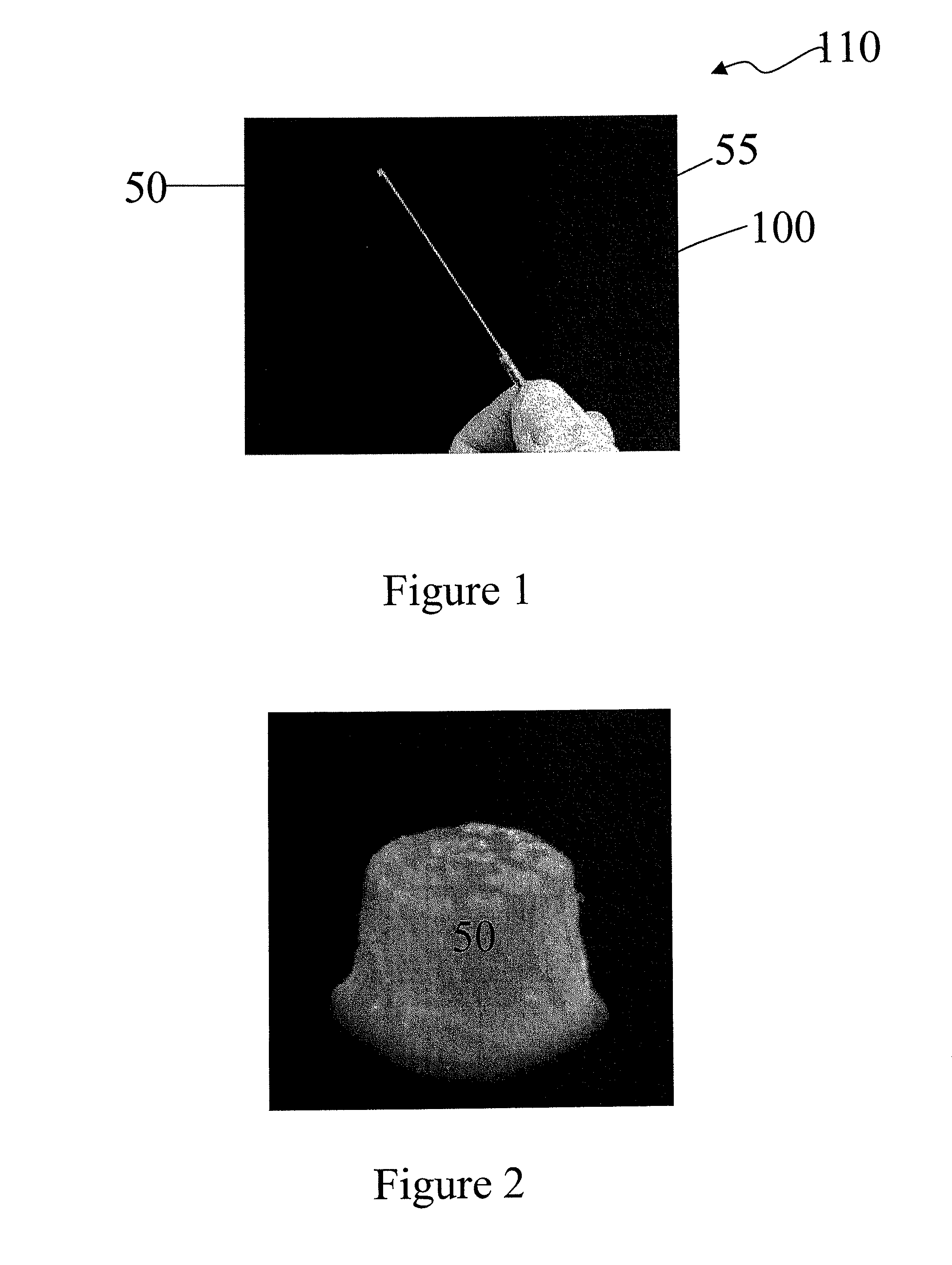
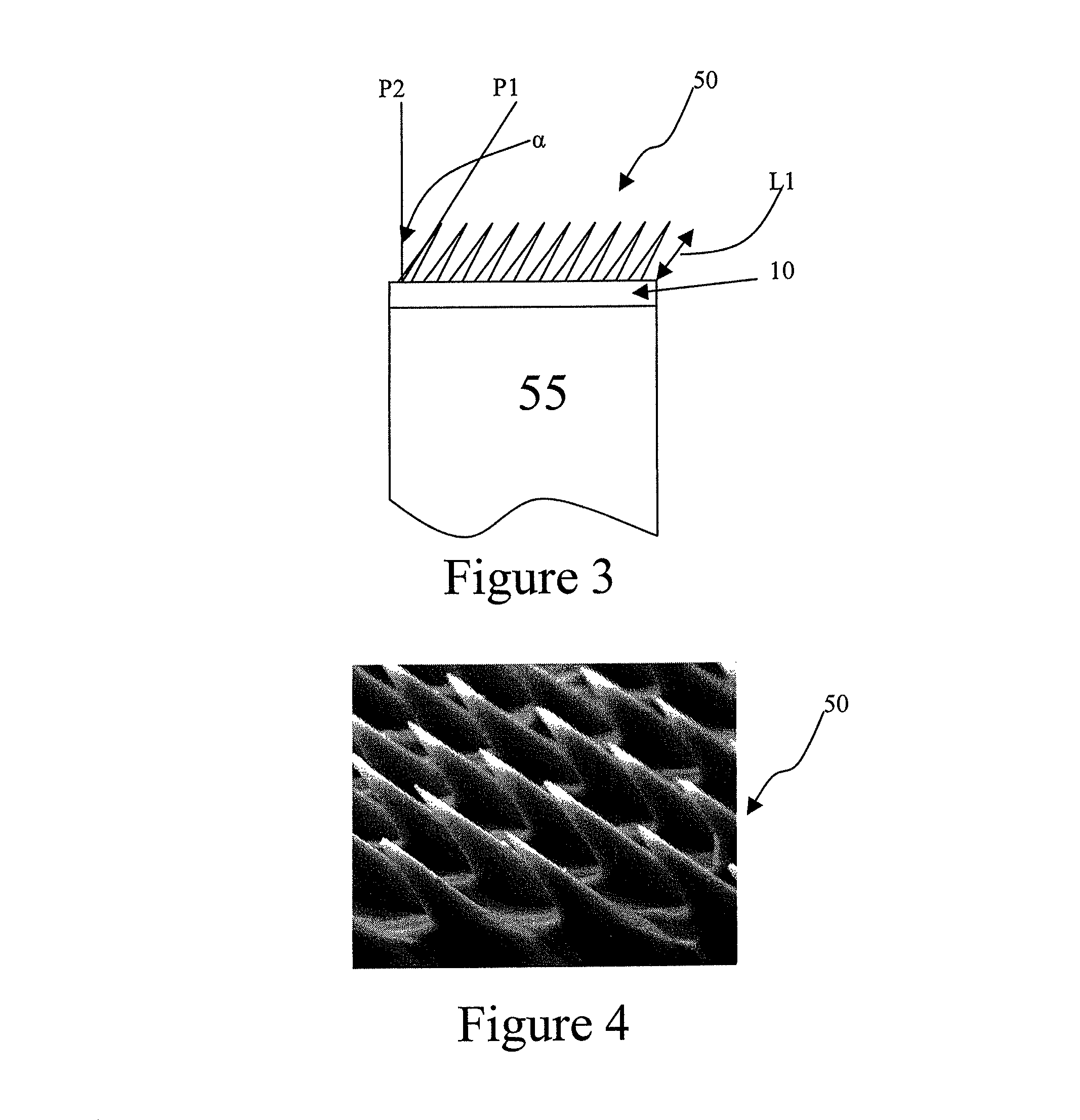
The present invention provides medical devices and methods for removing scarred tissue from an eye, particularly from the retina. The devices include an array of micro-needles or micro-spikes that can engage the scar tissue or the underlying tissue on which it is present, and can be smoothly peeled off or en bloc. The micro-needles have sharp features that can penetrate the scar tissue to a desired depth without damaging the non-targeted structures of the eye. The method involves inserting the micro-needle array into the eye and measuring the thickness of the scar tissue or the underlying tissue on which it is present. The device can also include a cannula engaged to the base of the micro-needle array. The invention provides a non-invasive and effective way to remove scar tissue from the eye.

Problems solved by technology

Significant bleeding may occur when an underlying vessel is damaged as a strongly adherent epiretinal membrane is peeled from the retina.
Removal of epiretinal membrane from the retina by manual peeling is technically demanding and difficult.
This anatomical relationship results in extremely minute tolerances in manual attempt to engage the membrane.
The application of too much pressure or misalignment of the position of the tip of the peeling instrument may result in a vision threatening injury that can result from damaging a portion of the retina, such as a region of the fovea.

Method used


Image

  • Retinal instrument
  • Retinal instrument
  • Retinal instrument

Examples


Embodiment Construction

[0041]Detailed embodiments of the present invention are disclosed herein; however, it is to be understood that the disclosed embodiments are merely illustrative of the invention that may be embodied in various forms. In addition, each of the examples given in connection with the various embodiments of the invention are intended to be illustrative, and not restrictive. Further, the figures are not necessarily to scale, some features may be exaggerated to show details of particular components. Therefore, specific structural and functional details disclosed herein are not to be interpreted as limiting, but merely as a representative basis for teaching one skilled in the art to variously employ the present invention.

[0042]The embodiments of the present invention relate to medical devices and methods for removing tissue, such as removing scar tissue from an eye. When describing the following structures and methods, the following terms have the following meanings, unless otherwise indicat...


PUM


Abstract

In one embodiment, the present invention provides a method of removing scar tissue from an eye that includes inserting a device including an array of micro-rods into an eye, wherein at least one glass micro-rod of the array of glass micro-rods includes a sharp feature; contacting a scar tissue with the array of micro-rods; and removing the array of micro-rods and the scar tissue from the eye. In another embodiment, the present invention provides a medical device for engaging a tissue including and an array of glass micro-rods, wherein at least one glass micro-rod of the array of glass micro-rods includes a sharp feature opposite a base of the array of glass micro-rods that is connected to the cannula, wherein the sharp feature of the at least one micro-rod is angled from a plane that is normal to a face of the base of the array of glass micro-rods.

Description

STATEMENT REGARDING FEDERALLY SPONSORED RESEARCH OR DEVELOPMENT[0001]This invention was made with Government support under Contract No. DE-AC05-00OR22725 awarded by the United States Department of Energy. The Government has certain rights in this invention.FIELD OF THE INVENTION[0002]The present invention in one embodiment relates to surgical instruments. In another embodiment, the present invention relates to a method of removing tissue, such as scar tissue from an eye.BACKGROUND OF THE INVENTION[0003]Repair of macular pucker or epiretinal membrane (ERM) is accomplished through vitreoretinal surgery. Using microsurgical instruments, a procedure known as vitrectomy or removal of vitreous gel from the posterior chamber of the eye is performed. Specialized microsurgical instruments are then used to gently peel and remove the scar tissue from the surface of the retina, relieving the traction and reducing the distortion to the retinal surface. The membrane peel involves identifying the ...

Claims


Application Information

Patent Timeline
Patent Type & Authority Patents(United States)
IPC IPC(8): A61F2/16
CPCA61F9/007A61F9/00736A61B17/205A61F9/00727
Inventor BRITTON, CHARLES L.D'URSO, BRIAN R.CHAUM, EDWARDSIMPSON, JOHN T.BABA, JUSTIN S.ERICSON, M. NANCEWARMACK, ROBERT J.
Owner UNIV OF TENNESSEE RES FOUND
Why Eureka
Eureka Blog
Learn More