Ultrahigh-speed cooling and rewarming method and ultrahigh-speed cooling and rewarming device

An ultra-high-speed, chip technology, applied in the field of biomedicine, can solve the problems that the processing results depend on the experience and technology of the operator, the uniformity of cooling inside the sample cannot be guaranteed, and it is difficult to ensure standardization and consistency, so as to achieve process consistency and surface Uniform heat transfer efficiency and good consistency

Pending Publication Date: 2018-11-30
成都酷卓生命科技有限公司
View PDF8 Cites 3 Cited by
  • Summary
  • Abstract
  • Description
  • Claims
  • Application Information

AI Technical Summary

Problems solved by technology

The existing cooling methods essentially obtain a higher cooling rate by pool boiling (Pool boiling) of the sample in liquid nitrogen, but a large amount of liquid nitrogen vapor will be generated to wrap around the sample during the pool boiling process, which is harmful to the sample. Further cooling produces heat insulation, so the heat transfer efficiency is low; the existing rewarming method generally drives the temperature rise through the temperature difference between the sample and the rewarming liquid, and the heat transfer efficiency is lower, and as the sample temperature rises, the temperature difference decreases , the rewarming rate de

Method used


Image

  • Ultrahigh-speed cooling and rewarming method and ultrahigh-speed cooling and rewarming device
  • Ultrahigh-speed cooling and rewarming method and ultrahigh-speed cooling and rewarming device
  • Ultrahigh-speed cooling and rewarming method and ultrahigh-speed cooling and rewarming device

Examples


Embodiment Construction

[0033] In order to make the object, technical solution and advantages of the present invention clearer, the present invention will be further described in detail below in conjunction with the accompanying drawings and embodiments. It should be understood that the specific embodiments described here are only used to explain the present invention, not to limit the present invention.

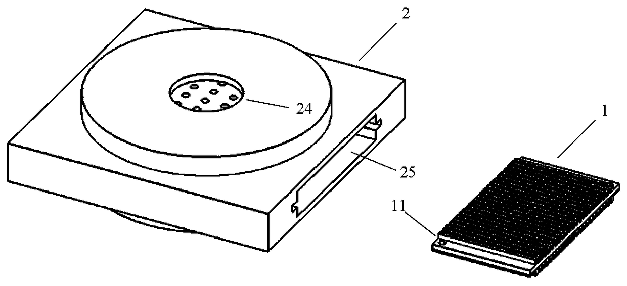
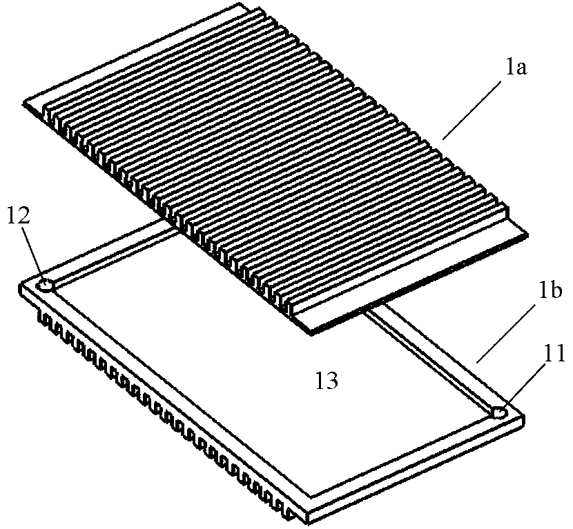
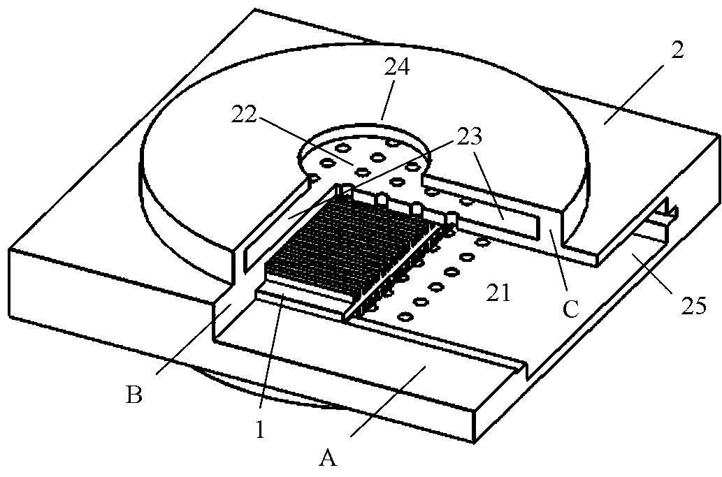
[0034] Such as figure 1 As shown, the ultra-high-speed cooling and reheating device in this embodiment includes a chip assembly 1 and an outer box 2 . The chip assembly 1 is formed by laser welding of chips 1a and 1b, such as figure 2 As shown, the thickness of 1a is 1 mm, and the thickness of 1b is 1.5 mm, and the materials are all copper. One side of the chip 1a is engraved with a parallel microchannel array, the channel depth is 0.75 mm, the width is 0.25 mm, and the channel wall thickness is 0.25 mm; one side of the chip 1b is engraved with the same microchannel array, and the other side is ...


PUM

PropertyMeasurementUnit
Thicknessaaaaaaaaaa
Embrittlement temperatureaaaaaaaaaa

Abstract

The invention relates to an ultrahigh-speed cooling and rewarming method and an ultrahigh-speed cooling and rewarming device, which are used for the glass-state storage of biological samples, such ascells and tissues. The device comprises a chip module and a case, and the chip module is arranged in the case. The chip module is of a flat hollow structure, and the interior is a sample micro-cavity,which is used for containing a to-be-stored biological sample; and a microchannel or micro-rod array is engraved on the external surfaces of the two sides with the largest area on the chip module, and are used for heat exchange. The case is also a flat hollow structure, and the interior is a chip cavity which is used for containing the chip module; one side of the chip cavity communicates with aworking medium inlet via a micropore array and a pressure-stabilizing cavity, and the other side communicates with a working medium outlet; the micropore array is aimed at the microchannel or micro-rod array on the surface of the chip module, and a jet gap exists between both. According to the invention, after being injected, working medium is jetted onto the chip module by the micro-rod array, asuperstrong surface heat exchange effect is generated under the dual function of the micro-jet and the microchannels, and thereby the ultrahigh-speed cooling and rewarming of the sample inside is realized.

Description

technical field [0001] The invention belongs to the technical field of biomedicine, and in particular relates to an ultra-high-speed cooling and rewarming method and device for vitrification and low-temperature storage of biological materials. Background technique [0002] Low temperature preservation is currently the only effective means for long-term preservation of many cells, tissues and other biological materials. Although biological materials can be stored safely at ultra-low temperatures for a long time, they are very likely to be severely damaged during cooling (from room temperature to ultra-low temperature) and rewarming (from ultra-low temperature to room temperature), which is the so-called low-temperature damage. With regard to the mechanism of low temperature damage, the academic community generally agrees that cell structure damage and solute concentration changes caused by the growth of ice crystals inside and outside cells are the main causes of low temperat...

Claims


Application Information

Patent Timeline
IPC IPC(8): F25D3/10F28D15/00A01N1/02
CPCA01N1/0252F25D3/10F28D15/00
Inventor 周小亮陈春蒋超杰王吉
Owner 成都酷卓生命科技有限公司
Why Eureka
Try Eureka