Microwave frequency structure for microwave tube with beam-containing device with permanent magnets and enhanced cooling

a technology of microwave frequency structure and beam-containing device, which is applied in the direction of travelling-wave tubes, electric discharge tubes, electrical apparatus, etc., can solve the problems of increasing the volume and weight of microwave frequency structure, weak point of cooling of these structures, and loss of microwave frequency power propagated in the microwave frequency structure of the tube in the form of heat, etc., to achieve simple production and enhance the cooling of the microwave frequency structure of the tub

Active Publication Date: 2013-04-23
THALES SA
View PDF9 Cites 2 Cited by
  • Summary
  • Abstract
  • Description
  • Claims
  • Application Information

AI Technical Summary

Benefits of technology

[0057]In another embodiment, the containing magnets e1, e2, . . . ei, . . . en, of transverse magnetization, comprise magnetic cores between the rows R1, R2, . . . Rp of containing permanent magnets, these cores being positioned, on the axes ZZ′ and YY′, in the middle of said containing magnets to increase the intensity of the magnetic field in the axis ZZ′.
[0061]A main objective of the invention is to enhance the cooling of the microwave frequency structures of the tubes that include a beam-containing device with alternating magnetic field.
[0062]Another objective of the invention is to produce a beam-containing magnetic device that is simple to produce with containment field performance levels that are equivalent to or better than those of the prior art devices.

Problems solved by technology

For example, when a TWT is operating, a portion of the microwave frequency power propagated in the microwave frequency structure of the tube is lost in the form of heat.
In both cases, the weak point of these structures is the cooling.
However, this cooling solution is reflected in an increase in the volume and the weight of the microwave frequency structure and notably of the electron beam-containing device, which is not always compatible with the application considered.
The structures with radially-magnetized permanent magnets include another drawback in their implementation because of the difficulty in producing magnetized rings with magnetization at all radial points.
An approximation can be produced by gluing a number of radially-magnetized segments to form a complete toroidal core, but the result is not as good.
This defect can be partially compensated by the introduction of an axially-magnetized ring A3 between two radially-magnetized rings.Finally, a production problem: rings with radial magnetization cannot be produced.

Method used


Image

  • Microwave frequency structure for microwave tube with beam-containing device with permanent magnets and enhanced cooling
  • Microwave frequency structure for microwave tube with beam-containing device with permanent magnets and enhanced cooling
  • Microwave frequency structure for microwave tube with beam-containing device with permanent magnets and enhanced cooling

Examples


first embodiment

[0086]FIG. 8a shows a partial view of a first embodiment, according to the invention, of a microwave frequency structure for microwave tubes, in this example a helix TWT.

[0087]The microwave frequency structure of FIG. 8a comprises a vacuum jacket 60 in the form of a cylindrical tube, of axis of revolution ZZ′. The vacuum jacket contains a cylindrical helix 62 secured in the jacket colinearly to the axis ZZ′ by insulating supports 64 and forming a propagation line for the microwave frequency wave from the TWT.

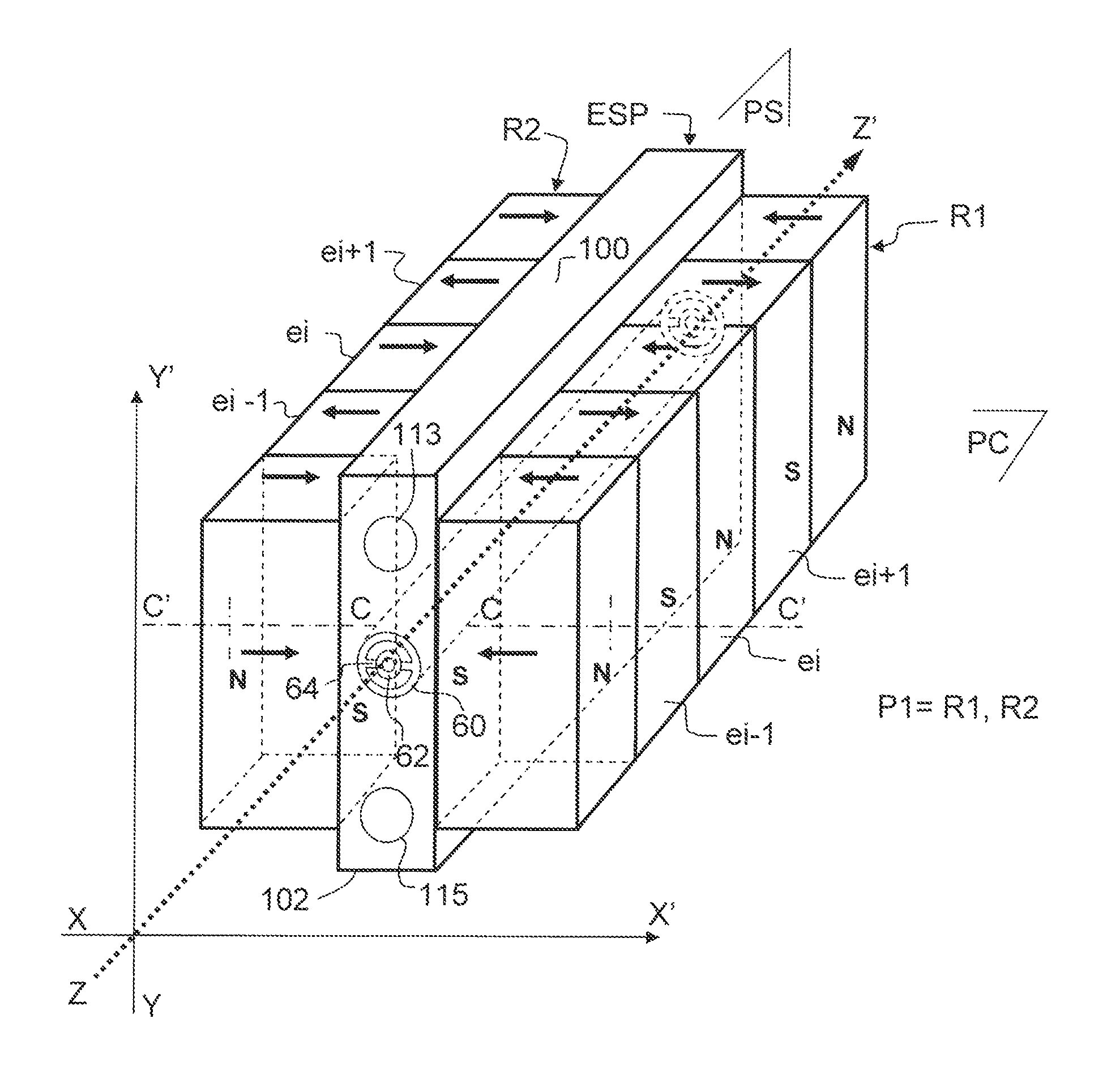
[0088]A TWT electron gun (not represented in the figure) generates an electron beam along the axis ZZ′ of the helix, also referred to hereinafter as electron beam containment axis. To this end, the microwave frequency structure comprises, according to a main feature of the invention, a pair P1 (or p=2) of rows of permanent magnets R1, R2 that are symmetrical in relation to the axis ZZ′. The rows R1, R2 either side of a plane of symmetry Ps passing through the containment axis ZZ...

second embodiment

[0114]FIG. 11a shows a perspective view of a second embodiment, according to the invention, of a microwave frequency structure for microwave tubes, in this example a helix TWT.

[0115]The microwave frequency structure of FIG. 11a comprises, as in the case of the first embodiment, the vacuum jacket 60 in the form of a cylindrical tube, of axis of revolution ZZ′.

[0116]In this second embodiment of FIG. 11a, the containing device comprises two pairs of rows of containing permanent magnets (or p=4), the first pair P1 comprising two rows R1, R2 and the second pair P2 comprising two other rows R3, R4. The rows are symmetrical in pairs relative to the axis ZZ′ and in the two perpendicular planes Pc, Ps passing through the axis ZZ′.

[0117]The magnetic polarizations of the containing permanent magnets e1, e2, . . . ei, . . . en, of the rows, in one and the same transverse plane relative to the axis ZZ′, have directions of axis CC′ passing through the axis ZZ′. In this second embodiment, the magn...

third embodiment

[0122]FIG. 12a shows a perspective view of a third embodiment, according to the invention, of a microwave frequency structure for microwave tubes, in this example a helix TWT.

[0123]The microwave frequency structure of FIG. 12a comprises, as in the case of the first and second embodiments, the vacuum jacket 60 in the form of a cylindrical tube, of axis of revolution ZZ′.

[0124]In this third embodiment of FIG. 12a, the containing device comprises two pairs of adjacent rows of containing permanent magnets e1, e2, . . . ei, . . . en, around the axis ZZ′, a first pair P1 comprising two rows R1, R2 and a second pair P2 comprising two other rows R3, R4.

[0125]Each containing permanent magnet of parallelepipedal shape comprises long sides 140 and short sides 142 perpendicular to the long sides. A long side 140 of a containing magnet ei of a row is in contact with a short side 142 of a containing magnet of another adjacent row so that the four magnets ei of the four adjacent rows R1, R2, R3, R...


PUM


Abstract

The invention relates to a microwave frequency structure for microwave tube comprising a cylindrical vacuum jacket and a device for containing an electron beam in the axis of revolution of the cylindrical jacket. The containing device comprises at least two rows, each containing permanent magnets, each row being aligned either side of and equidistant to the beam-containment axis, the at least two rows containing permanent magnets being of parallelepipedal shapes and having a magnetic polarization parallel to one of its edges in a plane transversal to the axis, their direction of magnetization in the row changing alternately from one containing magnet to another next containing magnet, or preceding containing magnet, to create an alternating periodic magnetic field along the containment axis.

Description

CROSS-REFERENCE TO RELATED APPLICATIONS[0001]This application is a National Stage of International patent application PCT / EP2008 / 067236, filed on Dec. 10, 2008, which claims priority to foreign French patent application No. FR 07 08741, filed on Dec. 14, 2007, the disclosures of which are hereby incorporated by reference in their entirety.FIELD OF THE INVENTION[0002]The invention relates to a microwave frequency structure for microwave tube comprising a containing device with permanent magnets for an electron beam from the tube with a configuration that allows enhanced cooling of said structure.BACKGROUND OF THE INVENTION[0003]A microwave frequency tube comprises a microwave frequency structure that is passed through by an electron beam generated by an electron gun. The electron beam is contained in a space where the interaction occurs between the electrons of the beam and an electromagnetic wave (traveling or standing), the field configuration of which wave is determined by the mic...

Claims


Application Information

Patent Timeline
Patent Type & Authority Patents(United States)
IPC IPC(8): H01J25/34
CPCH01J23/005H01J23/0873
Inventor DURAND, ALAINLE CLAIR, ALAIN
Owner THALES SA
Why Eureka
Try Eureka