Fixing structure for signal wires of a resolver

a technology of fixing structure and resolver, which is applied in the field of resolver, can solve the problems of motor generation and high heat to make the temperature rise, troublesome wire keeping process, etc., and achieve the effect of simplifying the manufacturing process and minimizing the requirement of wire keeping

Active Publication Date: 2013-04-23
HIWIN MIKROSYST
View PDF0 Cites 5 Cited by
  • Summary
  • Abstract
  • Description
  • Claims
  • Application Information

AI Technical Summary

Benefits of technology

[0007]It is therefore a primary object of the present invention to provide a fixing structure for signal wires of a resolver. With the fixing structure, after the coils are wound on the stator of the resolver, the requirement of wire keeping can be minimized so as to simplify the manufacturing process of the resolver.
[0008]It is a further object of the present invention to provide the above fixing structure for signal wires of the resolver. With the fixing structure, after the coils are wound on the stator of the resolver, the outward extending ends of the coils can be extended into the corresponding connection sections by shortest distance. Accordingly, the length of the extension lead can be shortened to reduce the amount of redundant wires.

Problems solved by technology

Accordingly, the wire keeping process is troublesome to complicate the manufacturing process.
Furthermore, in operation, the motor will generate high heat to make the temperature rise.

Method used


Image

  • Fixing structure for signal wires of a resolver
  • Fixing structure for signal wires of a resolver
  • Fixing structure for signal wires of a resolver

Examples


Embodiment Construction

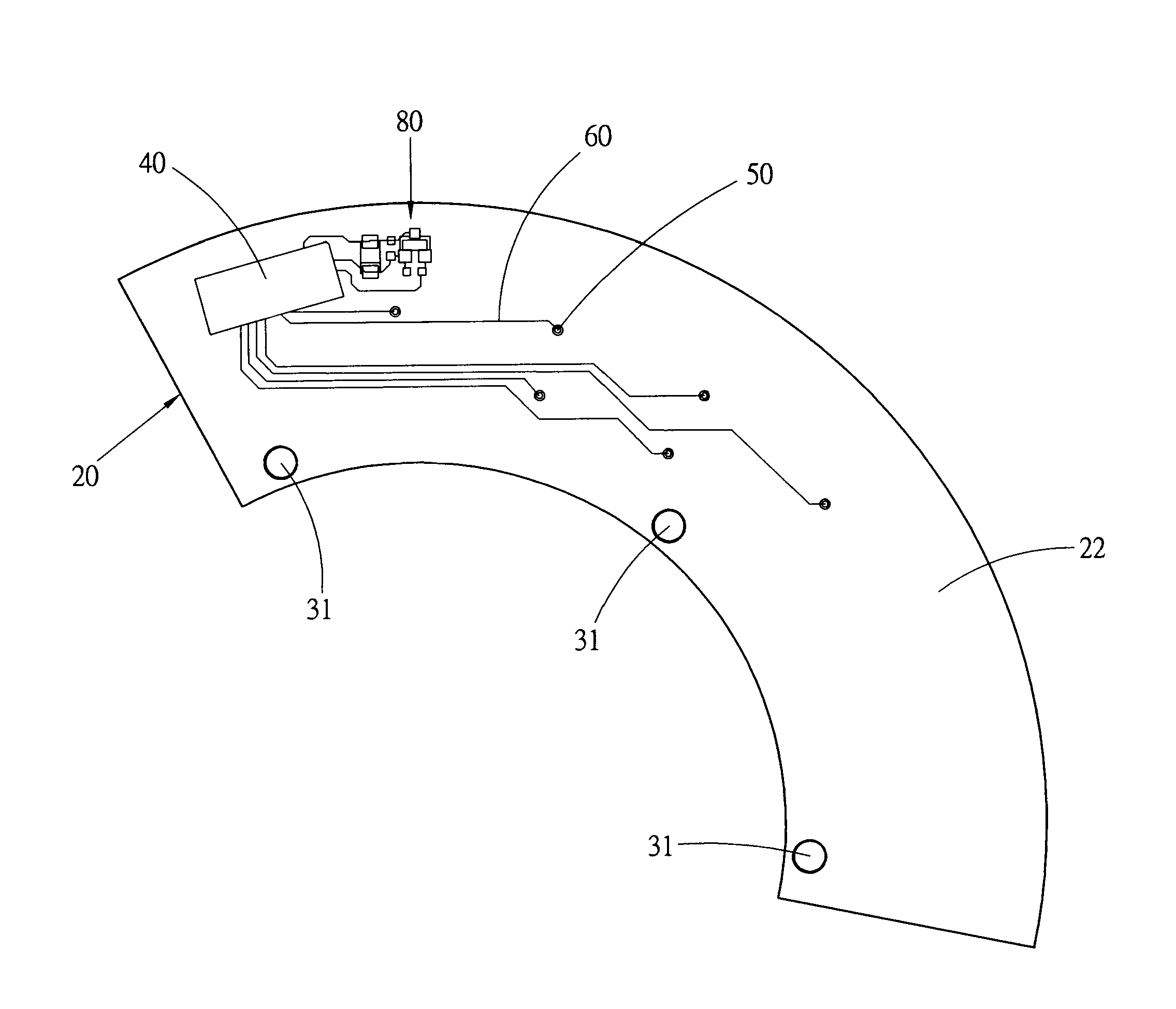
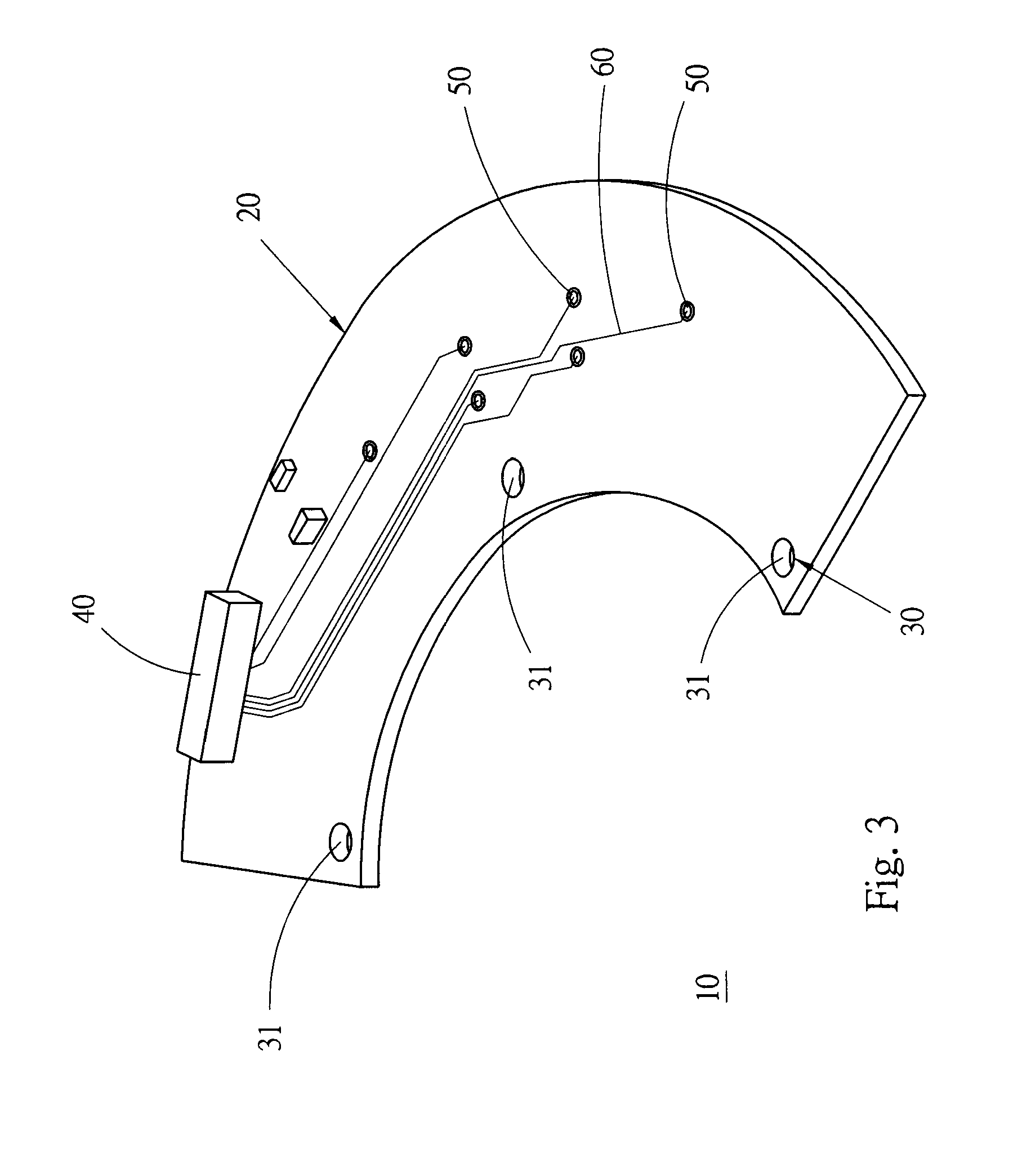
[0017]Please refer to FIGS. 3 to 6. According to a preferred embodiment, the fixing structure 10 for signal wires of a resolver of the present invention includes a circuit board 20, a fixing section 30, a connection terminal seat 40, multiple connection sections 50 and multiple bridge circuits 60.

[0018]The circuit board 20 is substantially an arcuate board member having a first board face 21 and a second board face 22. The first board face 21 is attached to an end face 71 of a resolver stator 70. The circuit board 20 has a curvature center coinciding with an axis of the stator 70. The circuit board 20 is such sized as to cover multiple coils 72 wound on the stator 70 and having outward extending ends. The outward extending ends are positioned within a projective range of the first board face 21 of the circuit board 20.

[0019]The fixing section 30 is used to fix the circuit board 20 with the end face 71 of the stator. The fixing section 30 has three fixing holes 31 formed through the ...


PUM


Abstract

A fixing structure for signal wires of a resolver is disposable on an end face of a stator of the resolver. The fixing structure includes a circuit board, a fixing section disposed on the circuit board for connecting the circuit board to the end face of the stator, a connection terminal seat disposed on the circuit board, multiple connection sections formed through the circuit board in the form of holes, and multiple bridge circuits respectively arranged between the corresponding connection sections and the connection terminal seat for bridging the corresponding connection sections and the connection terminal seat.

Description

BACKGROUND OF THE INVENTION[0001]1. Field of the Invention[0002]The present invention relates generally to a resolver, and more particularly to a fixing structure for signal wires of a resolver.[0003]2. Description of the Related Art[0004]A resolver is used as a feedback device of a feedback motor for feeding back angular position thereof. The resolver works in the principle that the energizing coil of the stator generates an energizing signal to have a flux linkage with the rotor. Then the induction coil of the stator creates an induced magnetic field to output an induction signal. The coils of the stator are formed generally by means of winding wires on the poles of the stator. The coils wound on the poles of the stator need to be further electrically connected to an exterior side. Therefore, after wound, the coils must be electrically connected to the exterior side via a connection member.[0005]FIGS. 1 and 2 show a conventional connection member 1 for electrically connecting the ...

Claims


Application Information

Patent Timeline
Patent Type & Authority Patents(United States)
IPC IPC(8): G01B7/30
CPCG01B7/30G01D5/204G01D11/245
Inventor LAI, MING-CHIHLI, CHI-LUWANG, CHIH-YU
Owner HIWIN MIKROSYST
Why Eureka
Try Eureka