Image pickup apparatus, on-vehicle image pickup apparatus, method and apparatus for manufacturing image pickup apparatus

a technology of image pickup and image, which is applied in the direction of cameras, television systems, instruments, etc., can solve the problems of reducing productivity, affecting the quality of image pickup equipment, and the relative positional relationship between the suction and the image pickup element may not be accurately determined, so as to achieve the effect of accurate relative position relationship and efficient manufacturing of such an image pickup apparatus

Active Publication Date: 2013-04-23
RICOH KK
View PDF42 Cites 5 Cited by
  • Summary
  • Abstract
  • Description
  • Claims
  • Application Information

AI Technical Summary

Benefits of technology

[0009]It is a general object of at least one embodiment of the present invention to provide an image pick up apparatus having an accurate relative positional relationship between a lens and an image pickup element, and an apparatus and a method for manufacturing such an image pickup apparatus more efficiently.

Problems solved by technology

However, in this technology, a relative positional relationship between the suction and the image pickup element may not be accurately determined.
As a result, more time may be required for locating them, resulting in lower productivity.
Further, since recent image pickup elements and substrates supporting them are increasingly reduced in sizes, the image pickup element supporting member such as a substrate may not include a sufficiently large area for suctioning the image pickup element.

Method used


Image

  • Image pickup apparatus, on-vehicle image pickup apparatus, method and apparatus for manufacturing image pickup apparatus
  • Image pickup apparatus, on-vehicle image pickup apparatus, method and apparatus for manufacturing image pickup apparatus
  • Image pickup apparatus, on-vehicle image pickup apparatus, method and apparatus for manufacturing image pickup apparatus

Examples


embodiments

First Embodiment

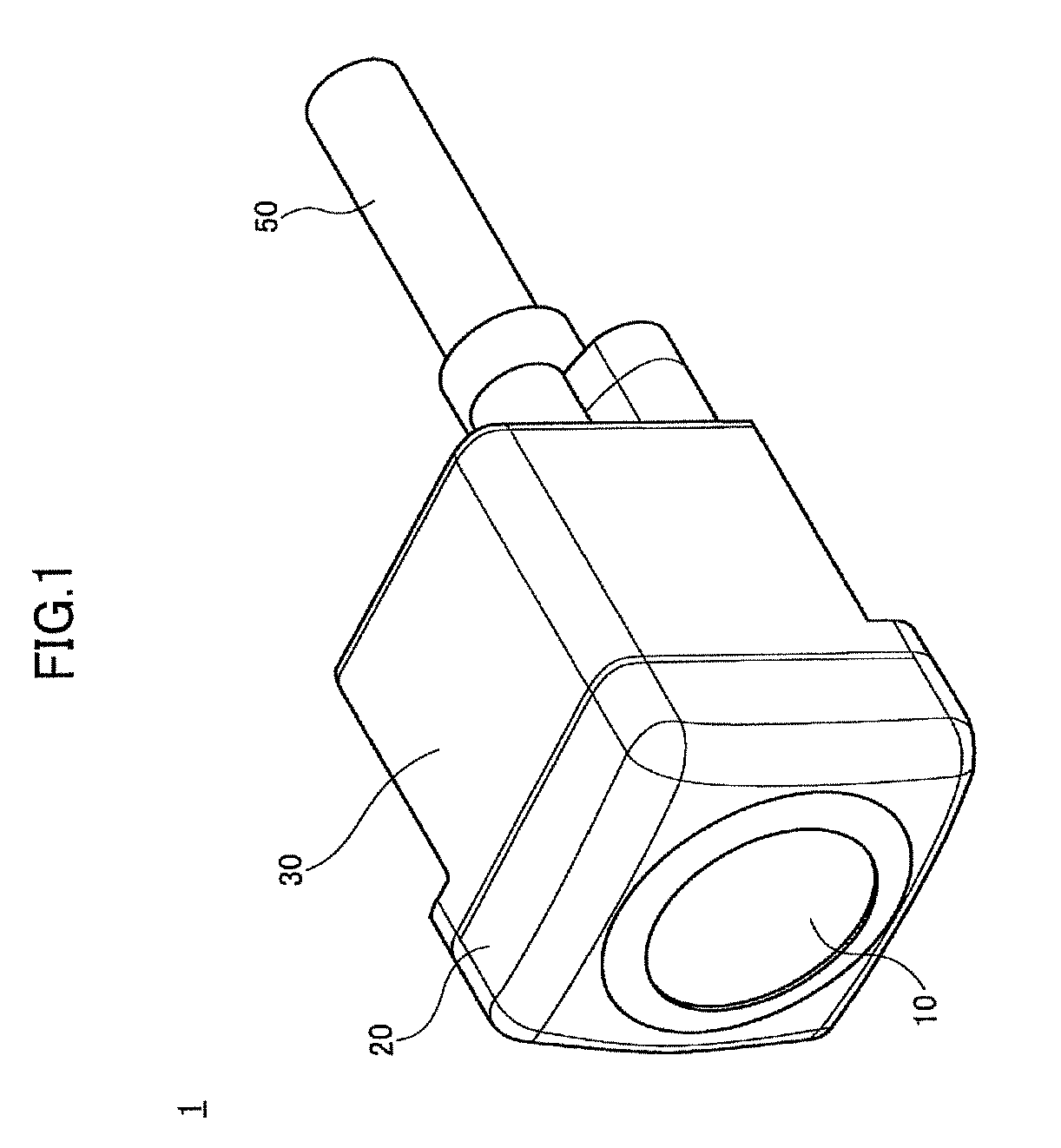
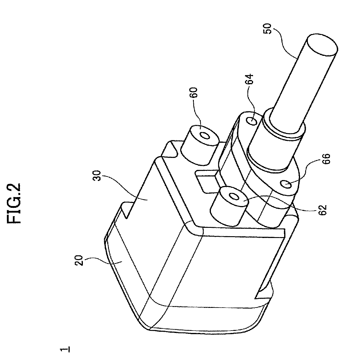
[0041]In the following, an image pickup apparatus, and method and apparatus for manufacturing the image pickup apparatus according to a first embodiment are described by referring to the accompanying drawings. The image pickup apparatus according to the first embodiment is provided at a rear portion of a vehicle as an on-vehicle camera, specifically, in the vicinity of a rear bumper or a car registration number plate, so that the on-vehicle camera can capture images of a diagonally downward area behind the vehicle. In this case, images captured by the image pickup apparatus (i.e., on-vehicle camera) are transmitted to an in-vehicle computer per age frame and the transmitted images are displayed on a liquid crystal display (LCD) located in the vehicle.

[0042]Note that the image pickup apparatus may be configured as an obstacle detection camera to capture forward areas of the vehicle. Note also that the image pickup apparatus according to the embodiments is not limited ...

second embodiment

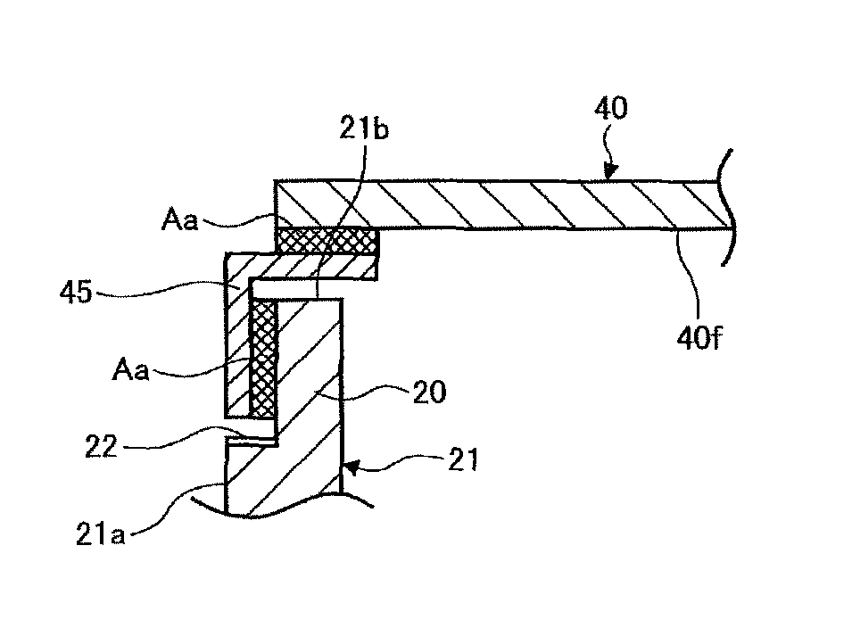
[0076]First, a second embodiment is described. As illustrated in FIGS. 12 and 13, an outer side surface 44 of the substrate 240 is made slightly smaller than the outer side surface 21a of the supporting wall 21 (of the lens cell 20). This point is the same as the first embodiment as illustrated in FIGS. 10C and 10D.

[0077]According to the second embodiment, the filler bonding structure portions SB (see FIG. 11) are configured such that the supporting wall 21 having a rear end surface 21b that faces a front surface 40f of a substrate 240 and an outer side surface 44 of the substrate 240 are bonded by supplying the thermosetting adhesive Ab as filler between the rear end surface 21b of the supporting wall 21 and the outer side surface 44 of the substrate 240.

[0078]Note that in FIGS. 12 and 13 illustrating the second embodiment, the indirect bonding structure portions SA (not shown, but provided positions are indicated by SA in FIG. 13) are provided in combination with the filler bondin...

third embodiment

[0083]Subsequently, a third embodiment is described. In this third embodiment, as illustrated in FIG. 14, the outer side surface 44 of the substrate 340 is located in an approximately the same line with the outer side surface 21a of the supporting wall 21 (of the lens cell 20). Further, third cutout portions 340a and 340b (adhesive filling cutout portions) are formed in an outer periphery of the substrate 340, avoiding the indirect bonding structure portions SA. In the areas where the third cutout portions 340a and 340b are formed, the thermosetting adhesive Ab is applied to the rear end surface 21b of the supporting wall 21 and side surfaces of the third cutout portions 340a and 340b of the substrate 340. Note that in the areas where no third cutout portions 340a and 340b are formed, the thermosetting adhesive Ab may be applied between the rear end surface 21b of the supporting wall 21 and a front surface 40f of the substrate 340, or the thermosetting adhesive Ab bonding may entire...


PUM


Abstract

A disclosed image pickup apparatus includes a first member holding a lens, and a second member holding an image pickup element converting an image formed via the lens into an electric signal, the second member having an approximately rectangular shape and two approximately arc-shaped location cutout portions at respective diagonal corners of the approximately rectangular shape. In the image pickup apparatus, the first and the second members are bonded via an indirect bonding structure portion where the first and second members are bonded via a fixing member with an ultraviolet curable adhesive and a filler bonding structure portion where the first and second members are bonded by supplying a thermosetting adhesive therebetween.

Description

BACKGROUND OF THE INVENTION[0001]1. Field of the Invention[0002]The invention relates to an image pickup apparatus and an on-vehicle image pickup apparatus utilized for on-vehicle cameras, digital cameras, digital camcorders, and the like, and a method and an apparatus for manufacturing such image pickup apparatuses.[0003]2. Description of the Related Art[0004]A related art image pickup apparatus having an image pickup lens and an image pickup element such as a Charge Coupled Device (CCD) and a Complementary Metal Oxide Semiconductor (CMOS) Device is widely used in on-vehicle cameras, digital cameras, digital camcorders, and the like.[0005]Such image pickup apparatuses are generally manufactured by a manufacturing apparatus having a fixed unit and a movable unit. In such a manufacturing apparatus, one of a member supporting the lens (lens supporting member) and a member supporting the image pickup element (image pickup element supporting member) is fixed on the fixed unit and the ot...

Claims


Application Information

Patent Timeline
Patent Type & Authority Patents(United States)
IPC IPC(8): H04N9/47H04N5/225H04N5/335
CPCH04N5/2253G03B17/02H04N23/54
Inventor NAKAJIMA, MITSURUTAKEMOTO, HIROSHISASAKI, NORIHIKOANDOU, YASUHIKOKANATANI, SHINOBUYOSHIDA, HAYATOSHIMIZU, KOHEI
Owner RICOH KK
Why Eureka
Try Eureka