Control of a boom construction and a tool articulated thereto

a technology of control levers and booms, which is applied in the direction of soil shifting machines/dredgers, lifting devices, transportation and packaging, etc., can solve the problems of slowing down the function and difficult simultaneous manipulation of several control levers, and achieves the effect of easy adjustment, simplified manipulation of control levers, and easy manipulation of machines

Active Publication Date: 2013-04-30
JOHN DEERE FORESTRY OY
View PDF39 Cites 14 Cited by
  • Summary
  • Abstract
  • Description
  • Claims
  • Application Information

AI Technical Summary

Benefits of technology

[0008]Thanks to the invention, the operator does not need to separately take care of changing the position of the felling head, when the position of the hoist boom and / or the stick boom is changed. The control system will automatically take care of maintaining the position of the felling head, for example, upright when the position of the hoist boom and / or the stick boom is changed. The control system allows the operator to change the position of the felling head.
[0009]The invention makes the work of the operator easier and faster. With the invention, the need for the operator to control the position of the felling head by an x-movement of one of the two control levers will become minimal. In practice, keeping the felling head straight, which requires accuracy and skill, will be a fully automatic function. The operator will only use the x-movement of the control lever primarily for unloading the bunches of trees collected in the felling head and for returning the felling head to the upright position.
[0010]The manipulation of the control levers can be simplified further, when the position of both the hoist boom and the stick boom is simultaneously controlled automatically by using only one control lever. This function is used for achieving a substantially linear movement of the head of the stick boom. Now, the felling head remains, for example, at a constant height when it is moved farther away or closer to the forest machine by means of both the hoist boom and the stick boom. The function is called a horizontal or parallel movement which is in most cases substantially horizontal and which is controlled, for example, by the control lever controlling the position of the hoist boom. In addition to the parallel movement, the control system also allows the operator to change the position of the hoist boom. In this way, the motion angle or height can be easily adjusted, if necessary, by the control lever for the hoist movement.
[0011]The automatic control of the position of the felling head and the functions of the parallel movement can be combined. Thus, the manipulation of the machine becomes very easy. By only one movement of the control lever (for example, the y-axis normally controlling the stick boom), the felling head can be driven outwards and inwards in the horizontal direction while the felling head remains in a set position, for example upright.
[0012]By means of the invention, it is possible to automate and combine functions, wherein the manipulation and operation of the boom system will be simpler and faster. The implementation is electronic and allows easy modification. The invention makes it possible to implement the levelling of a tool, for example the felling head, without sensors for measuring the position of the felling head, or at least the need for them is substantially reduced.
[0014]The invention can be applied, for example, in excavators, for controlling either a felling head that is available as an accessory for them, or the actual bucket. In excavators, the boom construction, the lower structure and the upper structure correspond to feller bunchers rather accurately.

Problems solved by technology

The simultaneous manipulation of several control levers is difficult and may slow down the function.

Method used


Image

  • Control of a boom construction and a tool articulated thereto
  • Control of a boom construction and a tool articulated thereto
  • Control of a boom construction and a tool articulated thereto

Examples


Embodiment Construction

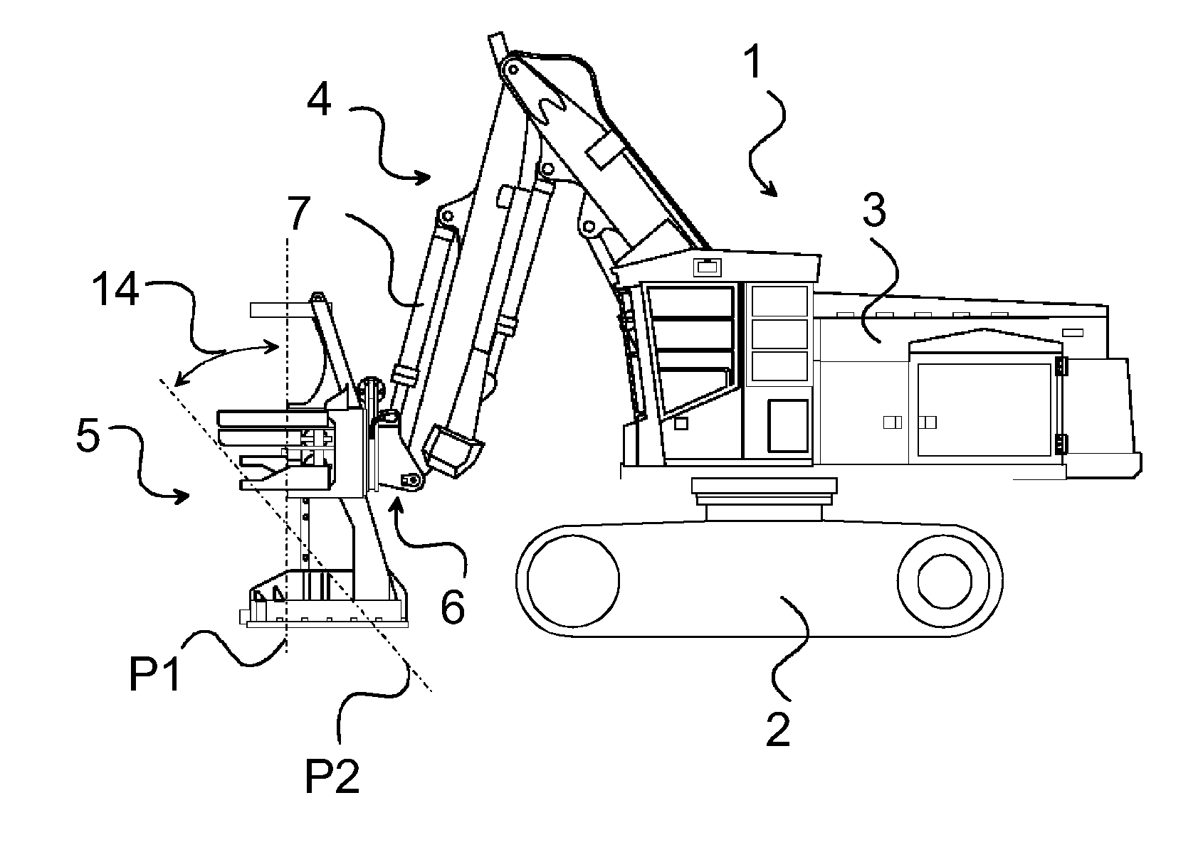
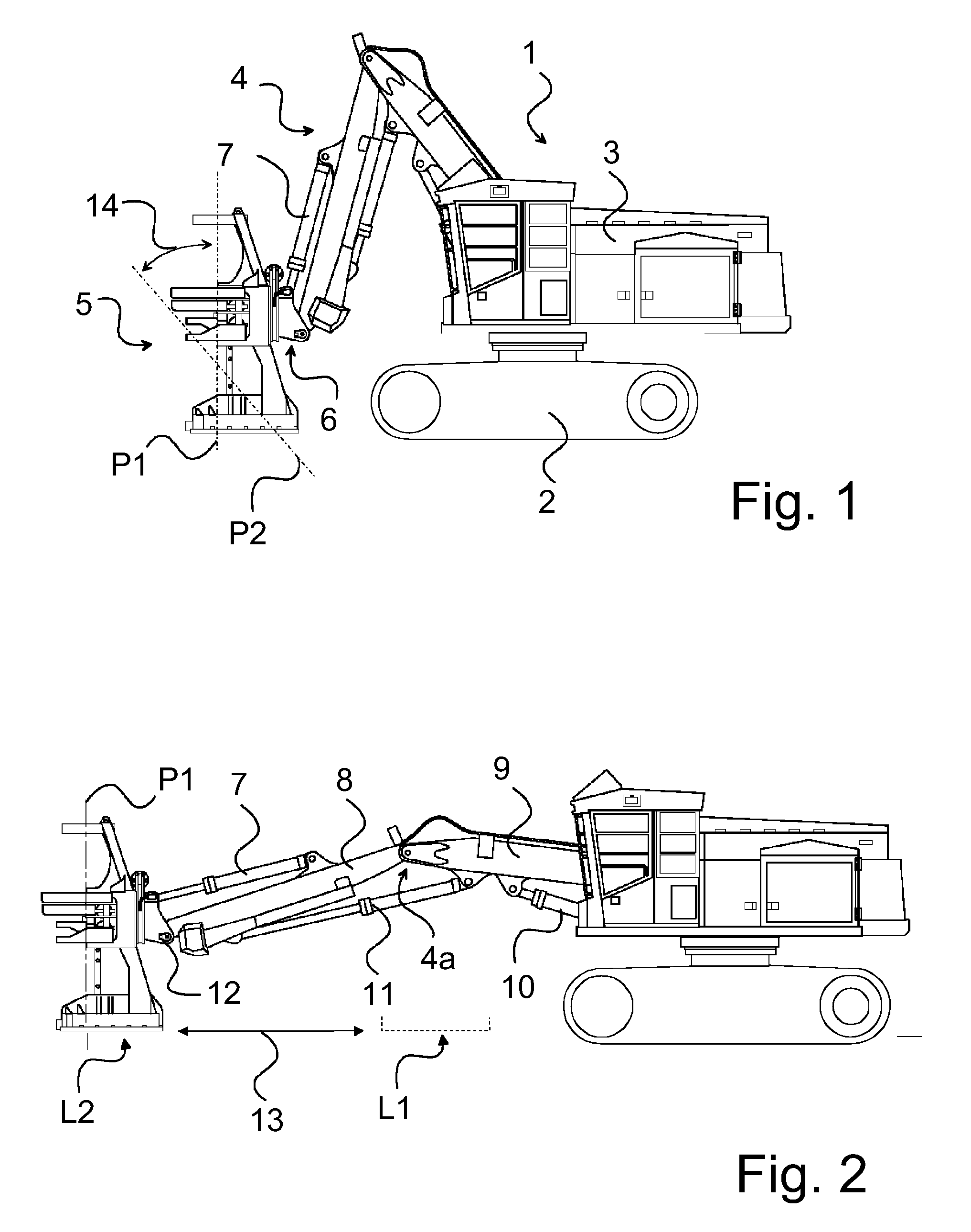
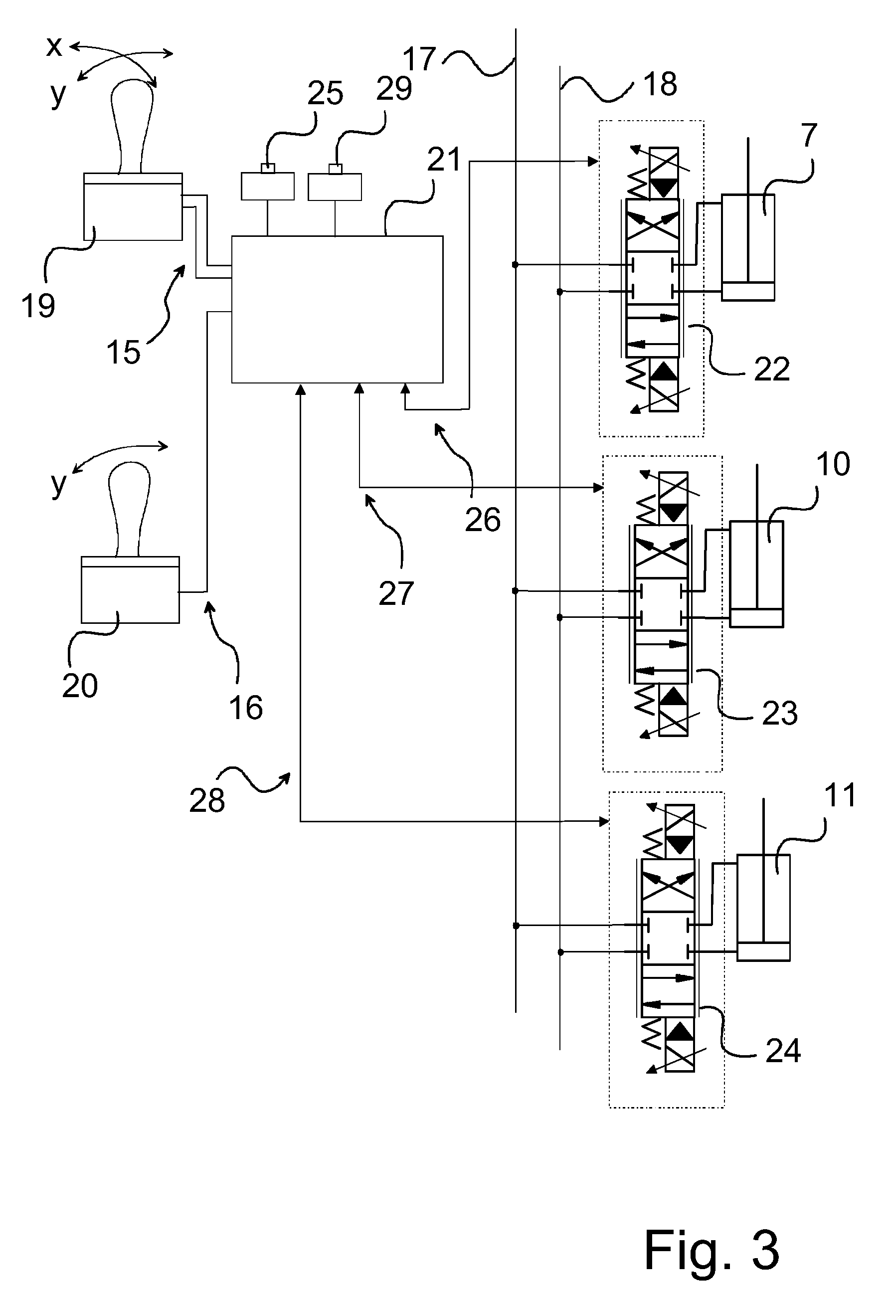
[0023]In the following, we shall describe in more detail the way of controlling the boom construction by means of the control system when the boom construction is coupled to a motor vehicle which is a working machine. Thus, a suitable tool is coupled to the end of the boom construction for accomplishing the work.

[0024]FIGS. 1 and 2 show a vehicle which is a forest machine and particularly a feller buncher 1. The feller buncher comprises a lower carriage 2, by means of which the feller buncher moves on a terrain. The lower carriage 2 is equipped with for example two caterpillar tracks. On top of the traverser of the lower carriage 2, an upper construction 3 is placed, comprising the cabin and the engine. A boom construction 4 is articulated to the upper structure 3. By means of the traverser, the upper structure 3 and the boom construction 4 can be rotated around a vertical line. The boom construction typically comprises two booms, which are also called a hoist boom and a stick boom ...


PUM


Abstract

A method for controlling a boom construction and a tool articulated thereto, the boom construction comprising a first boom and a first actuator controlling the same, a second boom articulated to the first boom, and a second actuator controlling the same, as well as a third actuator controlling the position of the tool, wherein in the method: the first actuator is controlled manually; and / or the second actuator is controlled manually and the third actuator is also controlled at the same time automatically to control the position of the tool. For example, the first actuator is controlled by use of a first set point; and / or the second actuator is controlled by use of a second set point; and in addition, the third actuator is controlled simultaneously by using for the control a variable dependent on at least one of said set points. For example, the control system of the boom construction and the tool articulated thereto comprises a control algorithm, which has been configured to determine the variable which is dependent on at least one of the set points.

Description

FIELD OF THE INVENTION[0001]The invention relates to a method for controlling a boom construction and a tool articulated thereto. The invention also relates to a system for controlling a boom construction and a tool to be articulated thereto.[0002]The invention relates to hydraulically controlled boom systems, to which a felling head is coupled, particularly a boom system for a feller buncher, and its control.BACKGROUND OF THE INVENTION[0003]Felling heads are widely used for the cutting and collecting of upright growing trees. In most cases, several tree trunks can be collected in the felling heads until the tree trunks are unloaded onto the ground. After this, the tree trunks are transported elsewhere by means of either a forwarder or a skidder. The boom system and the felling head are normally coupled to a high-power vehicle, such as a feller buncher, of which an example is given in U.S. Pat. No. 6,173,973 B1. Some felling heads are disclosed in documents US 2003 / 02025291 A1 and U...

Claims


Application Information

Patent Timeline
Patent Type & Authority Patents(United States)
IPC IPC(8): B66C23/00
CPCE02F3/436A01G23/081E02F9/2033E02F3/437B66C13/18B66C13/48
Inventor JANTTI, JARKKO
Owner JOHN DEERE FORESTRY OY
Why Eureka
Try Eureka