Stator with asymmetric poles and sensor oriented to more accurately determine position of rotor

a technology of asymmetric poles and sensors, applied in the field of electric machines, can solve the problems of more than compensating withdrawal, and achieve the effects of accurate synchronisation, small slot opening, and reducing stator inductance without lowering saturation poin

Active Publication Date: 2013-04-30
DYSON TECH LTD
View PDF25 Cites 1 Cited by
  • Summary
  • Abstract
  • Description
  • Claims
  • Application Information

AI Technical Summary

Benefits of technology

[0005]By orienting the sensor such that it is substantially parallel to the armature field lines passing through the sensor, the sensor is much less sensitive to the effect of armature reaction. In particular, the magnetic field sensed by the Hall-effect sensor is primarily that from a rotor of the electric machine. Accordingly, accurate synchronisation of phase energisation and rotor position may be achieved resulting in a more powerful and efficient electric machine. Moreover, since the sensor is less sensitive to the effect of armature reaction, the sensor is less sensitive to any current changes in a winding of the stator. Accordingly, the electric machine is able to perform efficiently, irrespective of the current in the winding.
[0006]The electric machine ideally comprises a permanent-magnet rotor having an interpole axis. As a consequence of orienting the sensor such that it is parallel to armature field lines, the interpole axis may intersect the plane of the sensor at a non-orthogonal angle. Consequently, the sensor is less sensitive to the magnetic field of the rotor. However, this drawback is more than compensated by the fact that the sensor is much less sensitive to the armature field. Accordingly, in spite of the reduced sensitivity to the rotor field, the sensor is nevertheless able to more accurately determine the position of the rotor.
[0009]For each of the aforementioned aspects, the poles may be separated by a slot opening, with the sensor then being located at the slot opening. The senor may be located adjacent the slot opening or within the slot opening. In being located adjacent the slot opening, a relatively small slot opening may then be employed. This then has the advantage that the poles of the stator capture a good portion of the magnetic flux from the rotor. In being located within the slot opening, a larger slot opening is typically required. However, the armature field lines within the slot opening are generally straighter than those outside the slot opening. Accordingly, by locating the sensor within the slot opening, the sensor can be oriented such it is much less sensitive to the armature field and thus much less sensitive to the effect of armature reaction.
[0010]Advantageously, each pole comprises a leading edge and a trailing edge relative to the direction of orientation of the rotor. The leading edge of each pole is then ideally thicker than the trailing edge. This form of asymmetry in the poles has the benefit of reducing the inductance of the stator without lowering the saturation point.
[0011]The electric machine is ideally suited for use with a battery. Since the sensor is much less sensitive to the effect of armature reaction, the sensor is much less sensitive to any changes in the winding current. Consequently, as the battery discharges, the electric machine is able to maintain accurate synchronisation of the phase energisation and rotor position.

Problems solved by technology

However, this drawback is more than compensated by the fact that the sensor is much less sensitive to the armature field.

Method used


Image

  • Stator with asymmetric poles and sensor oriented to more accurately determine position of rotor
  • Stator with asymmetric poles and sensor oriented to more accurately determine position of rotor

Examples


Embodiment Construction

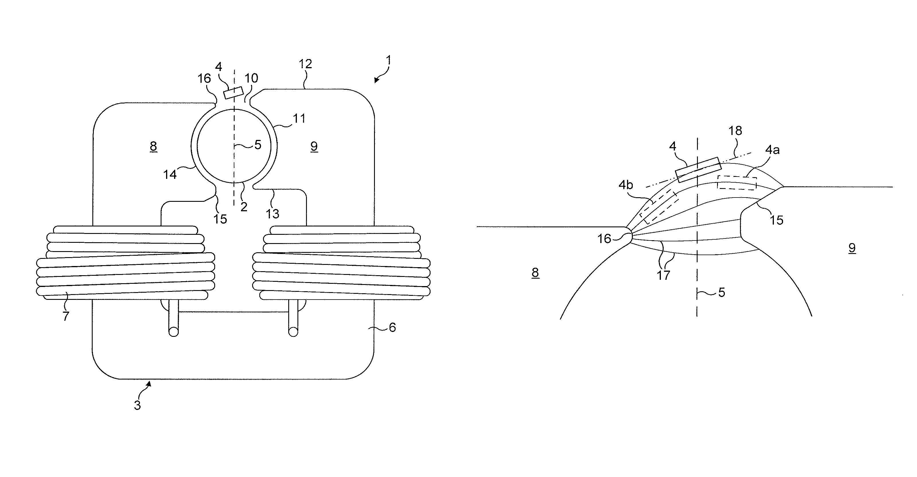
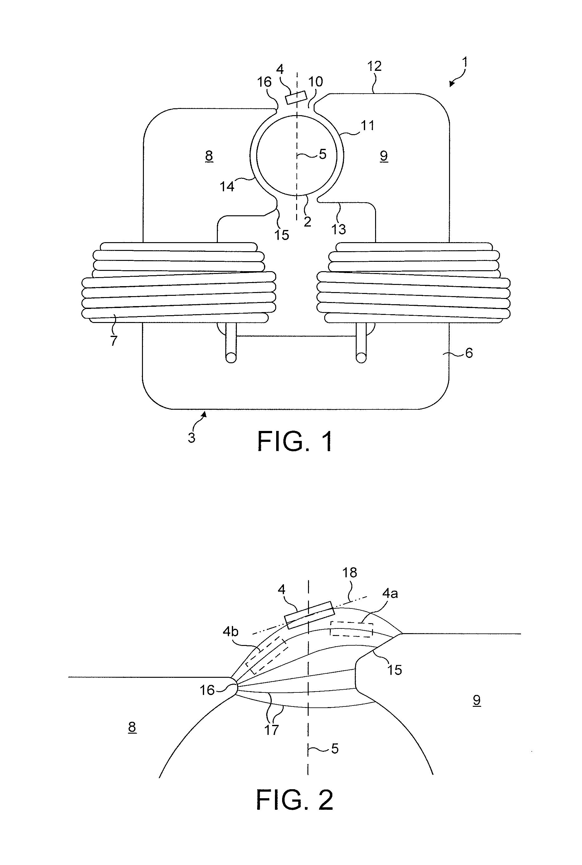
[0015]The motor 1 of FIG. 1 comprises a rotor 2, a stator 3 and a Hall-effect sensor 4.

[0016]The rotor 2 comprises a two-pole permanent magnet having an interpole axis 5.

[0017]The stator 3 comprises a stator core 6 about which a single-phase winding 7 is wound. The stator core 6 is c-shaped and comprises a pair of asymmetric poles 8,9 separated by a slot opening 10. Each pole 8,9 has a pole face 11, a first side 12 and an opposite second side 13 that extend from the pole face 11. Each pole face 11 includes an arcuate recess or pole arc 14, a leading edge 15 and a trailing edge 16 relative to the direction of rotation of the rotor 2. The leading edge 15 extends between the pole arc 14 and the first side 12 of each pole 8,9, and the trailing edge 16 extends between the pole arc 14 and the second side 13 of each pole 8,9. The pole arc 14 thus extends between the leading and trailing edges 15,16.

[0018]The leading edge 15 of each pole 8,9 is thicker than that of the trailing edge 16 in a...


PUM


Abstract

An electric machine that includes a stator and a Hall-effect sensor. The stator includes a pair of asymmetric poles and the sensor is oriented such that the plane of the sensor is substantially parallel to armature field lines passing through the sensor.

Description

REFERENCE TO RELATED APPLICATIONS[0001]This application claims the priority of United Kingdom Application No. 0903664.1, filed Mar. 3, 2009, the entire contents of which are incorporated herein by reference.FIELD OF THE INVENTION[0002]The present invention relates to an electric machine and in particular to the positioning of a Hall-effect sensor within the electric machine.BACKGROUND OF THE INVENTION[0003]The output power of an electric motor is critically dependant on accurate synchronisation of phase energisation and rotor position. Accordingly, the motor requires some means for accurately determining the position of the rotor. A relatively cheap solution is a Hall-effect sensor, which may be located at a slot opening between poles of the stator. However, owing to the effect of armature reaction, the sensor is sensitive to both the rotor field and the armature field. For a stator having asymmetric poles, the effect of armature reaction makes it particularly difficult to determine...

Claims


Application Information

Patent Timeline
Patent Type & Authority Patents(United States)
IPC IPC(8): H02K11/00
CPCH02K29/08H02K11/0021H02K11/215H02K1/08H02K21/12H02K1/12H02K1/27
Inventor CHEN, YUCELIK, TUNCAYCLOTHIER, ANDREW CHARLTONGREETHAM, STEPHEN
Owner DYSON TECH LTD
Why Eureka
Try Eureka