Stripping member, a stripping assembly and a method for extracting a particle beam from a cyclotron

a particle beam and stripping technology, applied in the field of stripping members and stripping assemblies, can solve the problems of limiting the maximum beam intensity that can be extracted, affecting the radio-activation efficiency of the cyclotron, and the septum interception of particles, so as to achieve the effect of increasing the extraction efficiency of the second stripper foil

Active Publication Date: 2013-04-30
ION BEAM APPL
View PDF7 Cites 9 Cited by
  • Summary
  • Abstract
  • Description
  • Claims
  • Application Information

AI Technical Summary

Benefits of technology

[0026]Advantageously, the stripping assembly further comprises adjusting means capable of adjusting the position of said stripping member within the cyclotron whereby increasing the extraction efficiency of said stripping member when said negatively charged particle beam is being stripped by said second stripper foil.
[0034]adjusting by means of adjusting means the positioning of said stripping member inside said charged particle accelerator so as to increase the extraction efficiency of said second stripper foil.

Problems solved by technology

However, this extraction method has two main drawbacks, as follows.
The first drawback is that the extraction efficiency of such a method is quite limited, thereby limiting the maximum beam intensity that can be extracted due to thermal heating of the septum by the intercepted beam.
The second drawback is that interception of particles by the septum contributes strongly to the radio-activation of the cyclotron.
However, the main drawback of this technique consists in that said method is complex.
In many applications, the energy of the ion beam generated by a cyclotron may not be fixed.
However, conventional stripping foils are very fragile due to extraction efficiency requirements and, consequently, are not capable of maintaining their physical properties during repeated ion hits.
Such repeated hits typically cause in fact excessive heating and, consequently, damages of stripper foils.
Moreover, when the vacuum condition of the accelerator is lost (during standard maintenance procedures or during the event of a sudden accidental vacuum loss, for example) the stripper foil typically cracks due to pressure variations.
As a consequence, the lifetime of conventional stripper foils is very short, and typical lifetime ranges are from a few hours to a few days, depending on the beam current intensity and density.
It is well known in the art that stripping foils having thickness between 2 μm and 5 μm have very high extraction efficiency but a very low durability (due to mechanical stress and / or heating due to repeated ion hits).
When the negative ion beam passes through the stripper foil, there are beam losses due to mechanism of multiple scattering.
Since the exit of the cyclotron has a very small diameter, if the emittance of the stripped particle beam is higher, a larger fraction of the particle beam may be lost because unable to pass through the exit of the cyclotron.
As mentioned before, conventional stripping foils are fragile and due to wear need to be replaced regularly.
Replacing a stripper foil is cumbersome and takes time: the vacuum inside the cyclotron is broken, the cyclotron is opened, human doses in maintenance must be taken, the stripper foil is replaced, the cyclotron is closed, and the cyclotron is pumped down until good vacuum is obtained.
However, this mechanism is too cumbersome for smaller cyclotrons like 18 MeV cyclotrons.
Moreover, in case of failure of a stripping foil, if the beam is not stopped, it hits and damages the vacuum chamber or other structures inside of the cyclotron.
In addition, the implementing of a probe for detecting a failure complicates the device and causes an additional bulk inside the cyclotron.
Such a probe in combination with such a rotating foil holder is not implementable in the reduced volume available inside a smaller cyclotron.
Another drawback of this solution brought by these authors is that even if the cyclotron is not opened, in the case of production of short half-life radioisotopes, it is important to minimize the time of replacing of the stripper foil and to avoid the stopping of the beam.

Method used


Image

  • Stripping member, a stripping assembly and a method for extracting a particle beam from a cyclotron
  • Stripping member, a stripping assembly and a method for extracting a particle beam from a cyclotron
  • Stripping member, a stripping assembly and a method for extracting a particle beam from a cyclotron

Examples


first embodiment

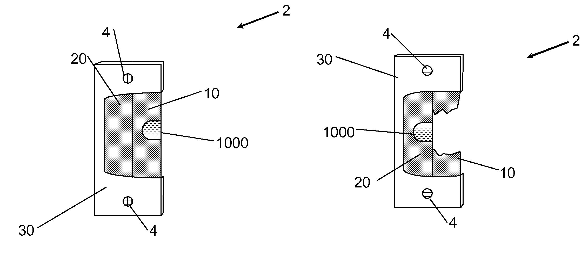
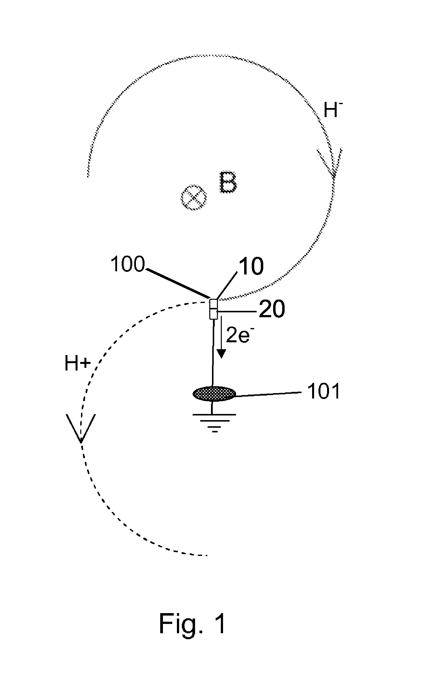
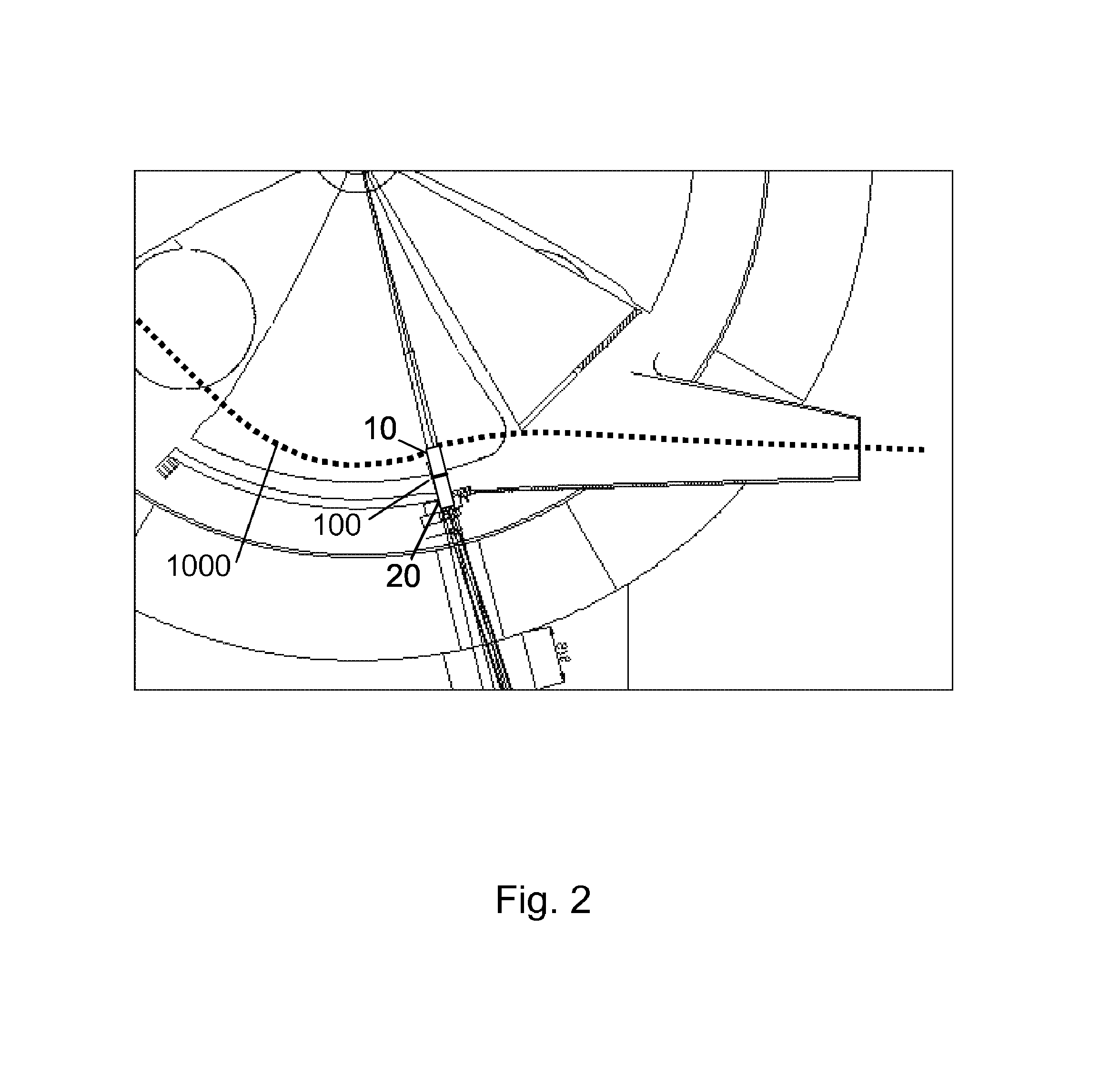
[0051]According to a second aspect of the present invention, a stripper assembly 1, as schematically shown in FIG. 5, is provided. The stripper assembly 1, comprises a support means, such as a stripper arm 40, for maintaining said stripping member 2, within the cyclotron, in the outer internal region thereof.

[0052]Adjusting means (not shown) for adjusting the position of the stripping assembly 1 and therefore the position of said second stripper foil 20 with respect to the incoming negative ion beam 1000 within the cyclotron may be further provided in order to decrease the dispersion of the stripped particle beam over the exit of the cyclotron and therefore increase the extraction efficiency of the second stripper foil 20. The adjusted position may be any position, linear or angular, e.g. linear along a radial direction with respect to the central axis, or angular around said central axis or around a horizontal axis.

second embodiment

[0053]According to the second aspect of the present invention, said stripping assembly 1 comprises, instead of the stripping arm 40, a stripper head 41 capable of supporting an additional second stripping member 3, the latter comprising a third stripper foil 11 and a fourth stripper foil 21, maintained by means of a second fork 31, as represented by FIG. 6. Said stripper head 41 is capable of rotating by means of driving means (not shown) around a vertical axis A perpendicular to the negative ion beam 1000.

[0054]Third stripper foil 11 and fourth stripper foil 21 of second stripping member 3 have the same characteristics as first stripper foil 10 and second stripper foil 20 of stripping member 2 respectively. According to this second embodiment, it is possible to rotate the stripping assembly 1 so as to intercept the negative ion beam 1000 either with stripping foils 10, of stripping member 2 or with stripping foils 11, 21 of second stripping member 3. As shown in FIG. 6 the negative...


PUM


Abstract

The present invention relates to a stripping member for stripping electrons off a negatively charged particle beam at the periphery of a cyclotron for extracting a particle beam out of said cyclotron, said stripping member comprising a first stripper foil adapted for being located at the periphery of said cyclotron so that said particle beam passes through said first stripper foil, characterized in that it comprises a second stripper foil adapted for being located side-by-side with the first foil at the periphery of said cyclotron at a more peripheral radius than said first stripper foil so that said negatively charged particle beam passes through said second stripper foil when said first stripper foil is damaged.

Description

CROSS REFERENCE TO RELATED APPLICATIONS[0001]This application is a national phase application of International Application No. PCT / EP2009 / 056670, filed May 29, 2009, designating the United States and claiming priority to European Patent Application No. 08157373.5, filed May 30, 2008, both of which are incorporated by reference herein in their entirety.TECHNICAL FIELD[0002]The present invention relates to the field of charged particle accelerators, such as a cyclotron. More particularly, the present invention relates to a stripping member, a stripping assembly as well as a method for extracting a particle beam from a cyclotron.DESCRIPTION OF RELATED ART[0003]Cyclotrons are largely used in many applications such as medical applications (e.g. production of radioisotopes or particle therapy), scientific research and industrial applications.[0004]A cyclotron is a re-circulation particle accelerator that works under high vacuum and accelerates ions up to energies of a few MeV, and even mo...

Claims


Application Information

Patent Timeline
Patent Type & Authority Patents(United States)
IPC IPC(8): H05H13/00
CPCG21K1/14H05H13/00H05H7/10
Inventor COLARD, VINCENT
Owner ION BEAM APPL
Why Eureka
Try Eureka