Image forming apparatus

a technology of forming apparatus and fixing roller, which is applied in the direction of electrographic process apparatus, instruments, optics, etc., can solve the problems of generating striation on an output image, easy formation of claw marks or claw scars on the surface of fixing members, and easy formation of scars on the fixing roller, so as to reduce waiting time, reduce the effect of excess air discharge, and improve the efficiency of controlling the fixing temperatur

Inactive Publication Date: 2013-04-30
RICOH KK
View PDF12 Cites 5 Cited by
  • Summary
  • Abstract
  • Description
  • Claims
  • Application Information

AI Technical Summary

Benefits of technology

[0019]In view of the above-mentioned problems, it is an object of at least one embodiment of the invention, in an image forming apparatus having a pneumatic piping provided with a relief valve, to effectively use excess air discharged from the relief valve, and to achieve long lives of a photosensitive body and its peripheral members, stabilization of a motion of a sheet, higher efficiency of controlling a fixing temperature of a sheet, and reduction of waiting time for cooling a fixing member.

Problems solved by technology

When using the separation claw, however, a claw mark or claw scar is easily formed on the surface of the fixing member because the separation claw contacts the fixing member.
As a result, there is a problem in that a striation is generated on an output image.
Therefore, a scar is not easily formed on the fixing roller even when contacted by the separation claw.
The surface layer with such a structure is soft and vulnerable.
In this case, a winding jam occurs, in which a sheet passes through a gap while tightly contacting the fixing member.
Therefore, a winding jam easily occurs due to an adhesion force increased by the stacked toner layers.
In particular, a sheet having a small blank space at a leading end part, on which no toner is attached; and a sheet on which a solid image such as a photograph is formed easily cause the winding jam due to their adhesion forces.
In any of these methods, however, there is a gap between the separation plate or separation claws and the fixing roller and fixing belt.
Therefore, a winding jam of the sheet occurs, or a jam is caused by the sheet hitting the separation plate or separation claw.
With this constitution, however, excess air has always been discharged from the relief valve while the compressor is operating, and wasted without being used.
Further, since a noise generated when the excess air is discharged is noisy, a silencer is required to be provided at a discharge outlet for noise control, which has been a factor to increase the cost.

Method used


Image

  • Image forming apparatus
  • Image forming apparatus
  • Image forming apparatus

Examples


first embodiment

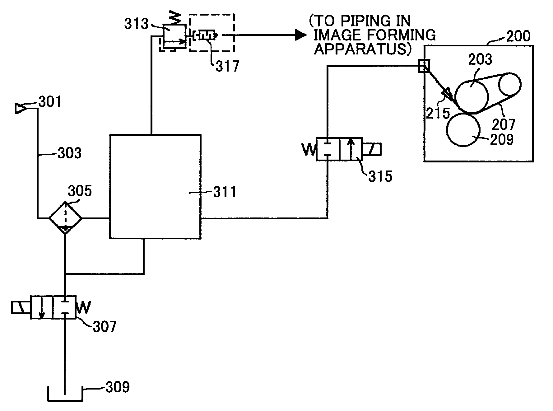
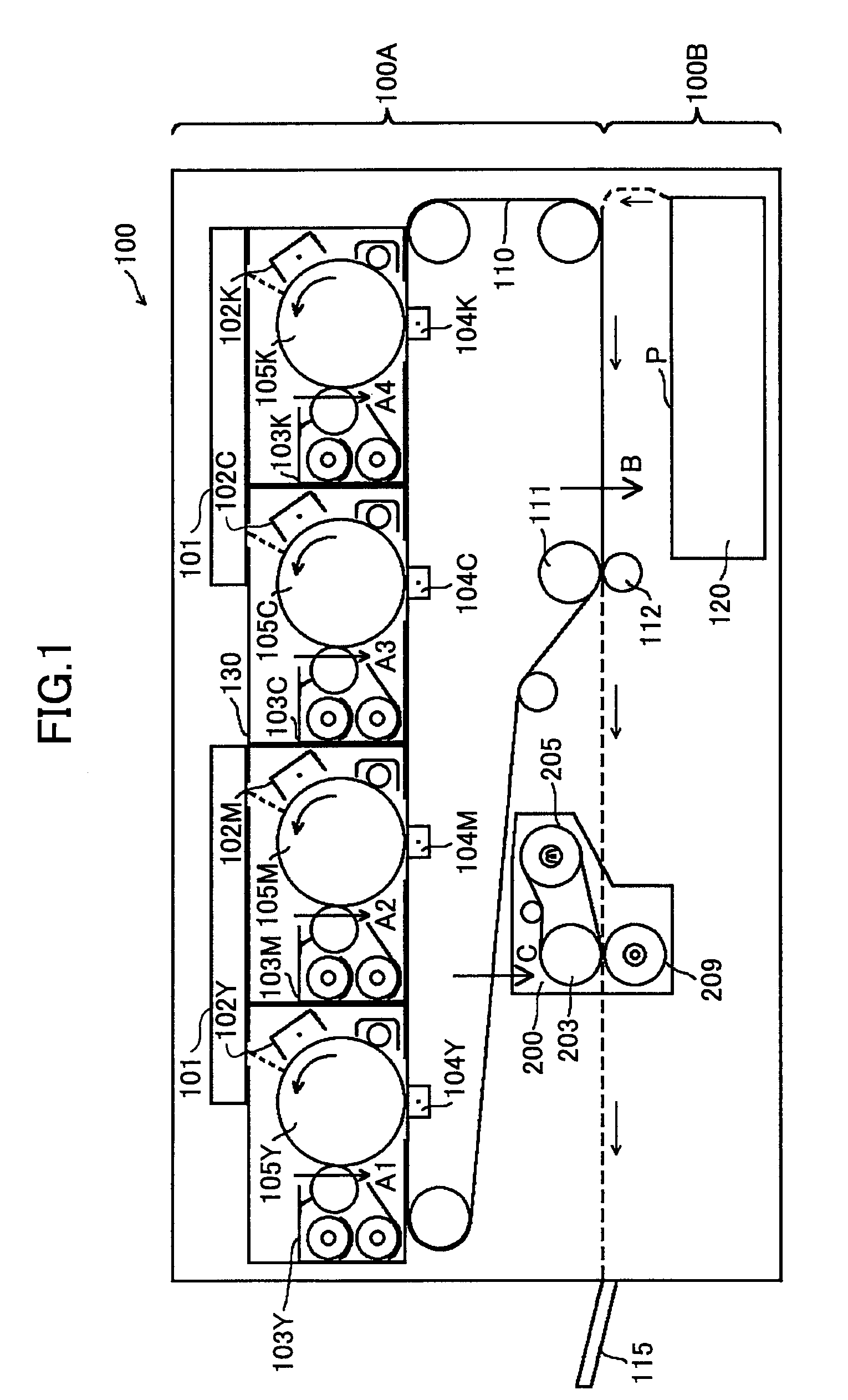
[0059]In a pneumatic piping according to the present invention, the compressor 301 is provided outside the image forming apparatus so that the compressor 301 sucks in air with a lower temperature and lower humidity than those inside the image forming apparatus. In addition, excess air discharged from the relief valve 313 is diverged and guided into areas A1, A2, A3, and A4 (see FIG. 1) in the peripheries of the photosensitive bodies 105Y, 105M, 105C, and 105K of respective colors of the image forming apparatus. Guide paths from a discharge outlet of the relief valve 313, at which a silencer is arranged, to the areas A1 to A4 are coupled by a pneumatic piping that is not shown. Therefore, excess air is guided via the guide paths into each box 130 that covers each of the imaging units from a rear or a front of inside the image forming apparatus, excluding writing light and a transfer part. As the pneumatic piping, a flexible hollow tube formed of polyurethane, nylon, or a fluororesin ...

second embodiment

[0061]In a pneumatic piping according to the present invention, the compressor 301 is provided in, for example, a heat generating high temperature part in the image forming apparatus, such as in a vicinity of the fixing device or an electrical transmission substrate, and a guide path (not shown) may be piped so that the excess air discharged from the relief valve 313 is guided to the sheet feed tray 120 as an area B (see FIG. 1). This guide path allows air at a relatively high temperature to be blown in a vicinity of the sheet feed tray 120, whereby the sheet P that has absorbed moisture can be dried to stabilize a motion of the sheet, a temperature of the sheet in a low temperature environment before the toner is fixed can be risen. Thus, power that had been required for fixation can be reduced by effectively using the excess heat. Note that the area B may be a conveyance path of the sheet P. The excess air may be blown to the sheet P conveyed in the conveyance path to dry the shee...

third embodiment

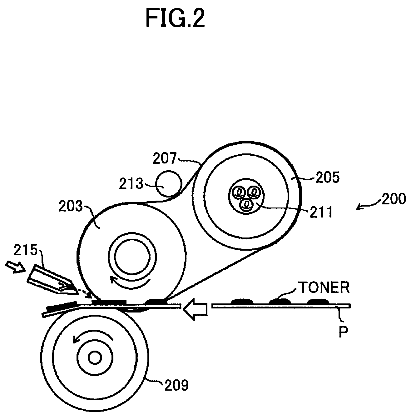
[0062]FIG. 4 shows a pneumatic piping according to the present invention. Here, the compressor 301 is provided outside the image forming apparatus. In addition, as shown in FIG. 4, an electromagnetic valve 401 that is a three-port electromagnetic valve is provided in the piping in the image forming apparatus, which is connected to the relief valve 313. Not only a guide path extending to the areas A1 to A4, but also a guide path extending to an area C is connected to discharge outlets of the electromagnetic valve 401. The electromagnetic valve 401 can switch these guide paths. The electromagnetic valve 401 can send the excess air to the areas A1 to A4 when a solenoid is demagnetized (not energized), and to the fixing device 200 as the area C (see FIG. 1) by a switching operation of the three-port electromagnetic valve when the solenoid is excited (energized).

[0063]By using the electromagnetic valve 401 as the switching unit of this piping and guide paths, there is a following effect....


PUM


Abstract

A disclosed image forming apparatus includes an image carrier; a developing device configured to form a toner image on the image carrier; a compressed air generating unit configured to generate compressed air; an air nozzle configured to eject the compressed air; a fixing device configured to fix the toner image on a sheet, the sheet being separated from the fixing device by the compressed air ejected from the air nozzle to the sheet; a pressure regulation unit provided between the compressed air generating unit and the air nozzle; and a guide path connected to the pressure regulation unit and configured to guide excess air generated by a pressure regulation of the pressure regulation unit to at least one part in the image forming apparatus.

Description

BACKGROUND OF THE INVENTION[0001]1. Field of the Invention[0002]The present invention generally relates to an image forming apparatus such as an electrophotographic printer, facsimile, and copier.[0003]2. Description of the Related Art[0004]Conventionally, as a device for fixing an unfixed toner image transferred on a sheet such as paper in these image forming apparatuses, a heat roller fixing device has been known and widely used. In the heat roller fixing device, while the sheet having the unfixed toner image is sandwiched and conveyed, the sheet is heated and pressurized by a fixing nip part formed of a fixing roller incorporating a halogen heater and the like and a pressure roller that pressurizes the fixing roller, so that the toner image is fixed.[0005]Moreover, a belt fixing device has also been known. In the belt fixing device, an endless fixing belt is stretched by a heating roller incorporating a halogen heater and the like and a fixing roller, and a fixing nip part formed...

Claims


Application Information

Patent Timeline
Patent Type & Authority Patents(United States)
IPC IPC(8): G03G15/20
CPCG03G15/2039G03G21/206
Inventor SETO, TAKASHIYAMAMOTO, TAKESHIHASEGAWA, KENICHIHIROSE, FUMIHIRO
Owner RICOH KK
Why Eureka
Try Eureka