Case sealer tape applicator

a tape applicator and sealing equipment technology, applied in the direction of roof tools, rigid containers, record information storage, etc., can solve the problem of time-consuming operation of replacing the depleted roll with a new roll, and achieve the effect of reducing down time and safety hazards, and simple and effective approach

Active Publication Date: 2013-05-07
LAMUS ENTERPRISES
View PDF5 Cites 1 Cited by
  • Summary
  • Abstract
  • Description
  • Claims
  • Application Information

AI Technical Summary

Benefits of technology

[0005]The invention provides a simple and effective approach to replenishing the tape in case sealing applications and reducing down time and safety hazards.
[0006]This invention is related to a tape applicator or tape head which is a combination of two separate apparatuses with snap-on engagement to obtain the interactive motion of a conventional tape applicator i.e. the present invention separates a conventional tape applicator into two separate portions with specific functionality to serve the purpose of quick tape change and reduce safety hazards.
[0009]One or more detachable units each with a fresh tape roll installed may be available for a single stationary unit and each detachable unit used as required to replace a detachable unit with depleted tape. The detachable units facilitate quick tape roll replenishing and minimize machine down time.
[0010]The operator has only to remove and replace the detachable unit from the machine as opposed to the entire tape head as in the prior art, thereby making tape replacement easier and quicker. Since the stationary unit contains the cutting mechanism; and remains with the machine, a significant safety advantage is provided as when the operator installs the new tape on the detachable unit he cannot be injured by the cutting blade, since there is no cutting blade on the detachable unit.

Problems solved by technology

Obviously replacing the depleted roll with a new roll is a time consuming operation as it involves threading the lead end of the tape from the new roll through the tape applicator.

Method used


Image

  • Case sealer tape applicator
  • Case sealer tape applicator
  • Case sealer tape applicator

Examples


Embodiment Construction

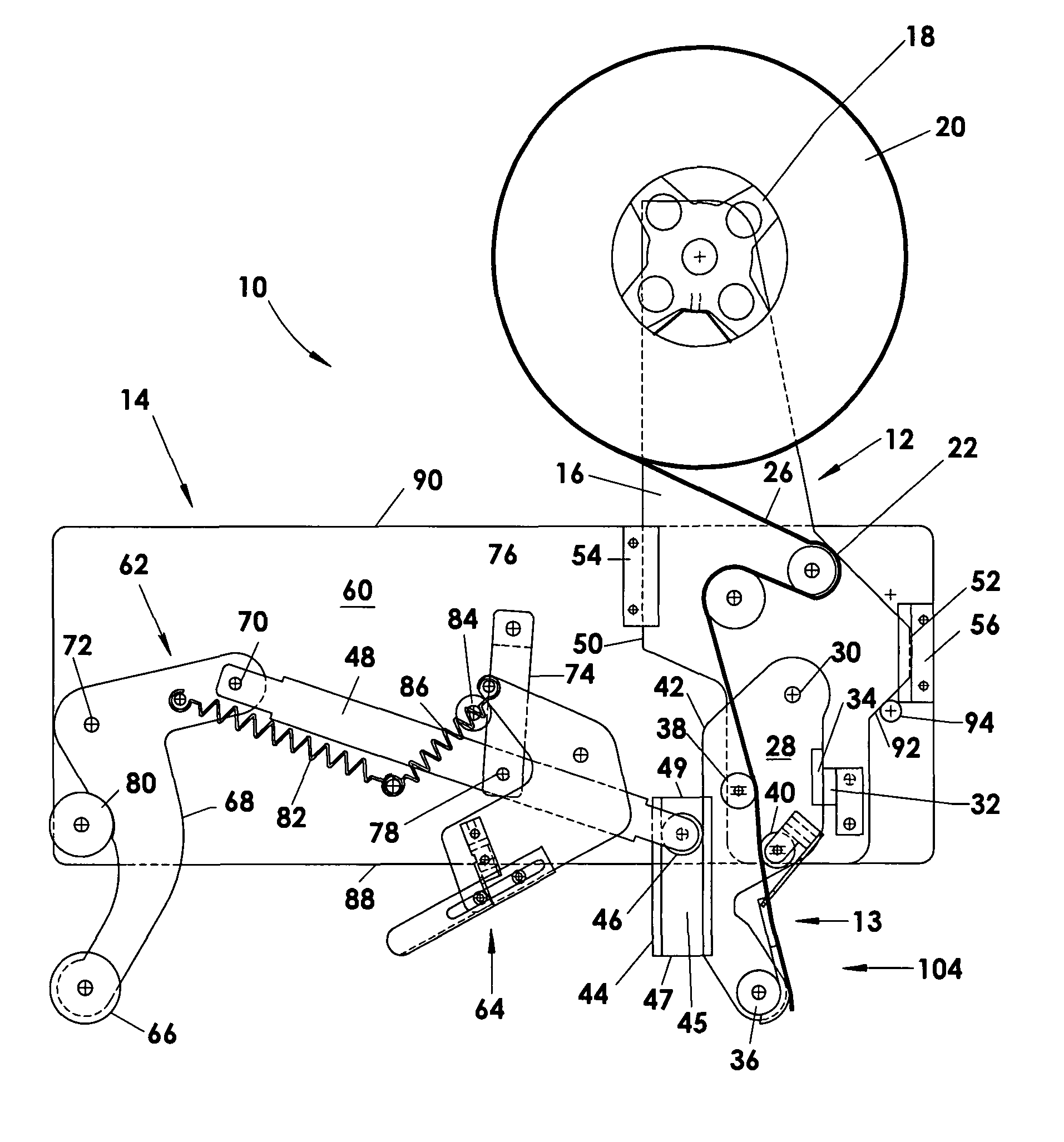
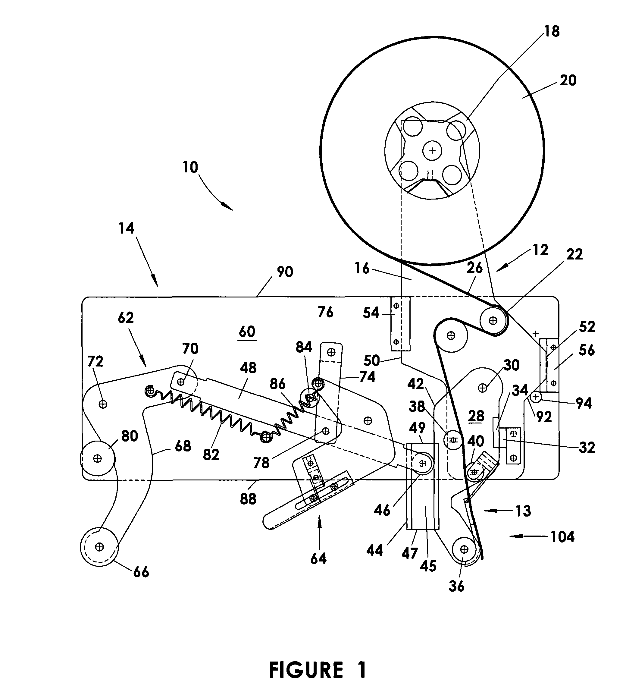
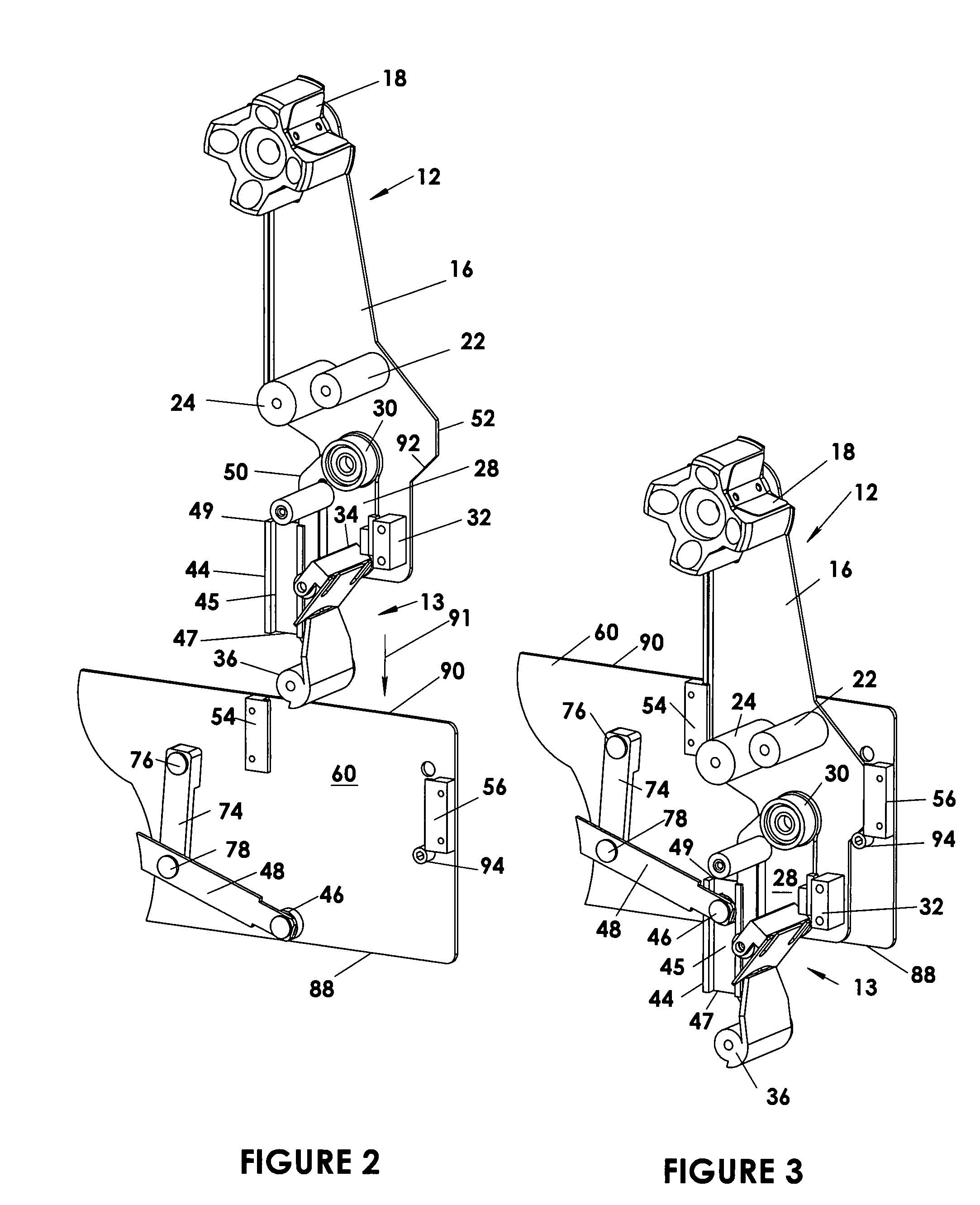
[0025]As shown in the drawings the tape applicator 10 of the present invention is composed of two units a detachable unit 12 that is removeably mounted in a stationary unit 14 that is fixed to the machine (not shown) in which the tape applicator is to be used. (See FIGS. 1 to 5, FIGS. 1 to 3 showing a top tape applicator and FIGS. 4 and 5 a bottom tape applicator).

[0026]The detachable unit 12 is formed by an auxiliary frame 16 on which is mounted a front portion 13 of the tape applicator mechanism. This front portion 13 (front in that it is used to apply tape to the front end 102 of the box 100 as it moves through the tape applicator 10) includes. a tape roll holder 18 for mounting a roll of tape 20 and tape guiding rollers 22 and 24 if required around which the tape 26 is passed. A front link 28 is pivotably mounted to the auxiliary frame 16 on axel 30 and forms part of the front portion 13. This front link 28 is releasably held in place for insertion and removal from the stationar...


PUM

PropertyMeasurementUnit
lengthaaaaaaaaaa
timeaaaaaaaaaa
magneticaaaaaaaaaa

Abstract

This invention relates to a tape applicator or tape head formed from a combination of two separated apparatuses namely a detachable unit containing a front portion of the tape applicator and a stationary unit containing a rear portion of the applicator with snap-on engagement there between to obtain the interactive motion of a conventional tape applicator i.e. the present invention separates a conventional tape applicator into two separate portions which results in the ability to quickly change tapes and reduces safety hazards.

Description

FIELD OF INVENTION[0001]The present invention relates to an improve tape applicator for case sealing equipment, more particularly to a tape applicator that facilitates changing of the tape roll to improve the efficiency of the equipment.BACKGROUND OF THE PRESENT INVENTION[0002]Conventional tape applicators or tape heads used for applying adhesive tapes to a box or carton or the like to seal the box flaps in closed position generally include a front link, having a wiper roll to apply the leading end of the tape to the leading face a carton moved relatively past the tape head, a trailing arm with a wiper roll for wiping the tape on the adjacent surface of the box and along the trailing end of the box and a cut off knife between the two arms and actuated to cut the tape to the proper length and with a free end adjacent to the wiper roll on the front link in a position to be applied to the next box. These applicators are common in the industry and have been found to operate very well. S...

Claims


Application Information

Patent Timeline
Patent Type & Authority Patents(United States)
IPC IPC(8): B32B37/00
CPCB65B51/067B65H35/0013B31B2201/6073Y10T156/17B65H2402/63Y10T156/1795Y10T156/1707B65H2402/30B31B50/72B65H2402/60
Inventor LAM, JOE AUGUSTINE S. T.
Owner LAMUS ENTERPRISES
Why Eureka
Try Eureka