Voltage buck-boost switching regulator

a switching regulator and voltage buck technology, applied in the field of switching regulators, can solve the problems of increasing the order of frequency transfer functions, increasing the cost, and affecting the operation, and achieve the effect of stable, high-speed, high-efficiency constant-voltage output operation

Active Publication Date: 2013-05-07
TEXAS INSTR INC
View PDF5 Cites 155 Cited by
  • Summary
  • Abstract
  • Description
  • Claims
  • Application Information

AI Technical Summary

Benefits of technology

[0021]A general object of the present invention is to solve the aforementioned problems of the prior art by providing a voltage buck-boost switching regulator that can perform a stable, high-speed, high-efficiency constant-voltage output operation without using a complicated, large-scale and high-cost phase compensation circuit.
[0025]Corresponding to the inductance current flowing in the inductance element, that is, corresponding to the current mode, the voltage buck-boost switching regulator of the present invention performs either a voltage reducing operation or a voltage boosting operation. With said current mode system, in the frequency characteristics, the secondary poles are divided into two poles, a low frequency pole and a high frequency pole. Consequently, a single integrator can be used to form the phase compensation circuit, and it is possible to output a stable, high-speed constant voltage using an integrator typically consisting of a resistor and a capacitor.
[0026]Also, in an aspect, while a transition from voltage reducing mode to voltage boosting mode or a transition from voltage boosting mode to voltage reducing mode can be performed smoothly during the continuous switching operation, in the state in which the input voltage and the output voltage are approximately equal, the switching operation of the voltage reducing switching circuit and the voltage boosting switching circuit is entirely stopped, so that the high efficiency constant-voltage output operation (through operation) can be performed without switching losses.

Problems solved by technology

Consequently, compared with the voltage reducing operation, the operation tends to become more unstable, and a solution is required.
However, because the number of circuit elements of phase compensation circuit 116 is increased, not only does the cost increase, but also the order of the frequency transfer function increases, and it becomes quite difficult to set the optimum constants in phase compensation circuit 116 to ensure stable operation over the entire region of the wide output voltage range from voltage reducing to voltage boosting.
However, according to this scheme, the number of the plural phase compensation circuits is increased, so that the circuit scale becomes even larger, and the size and cost of the semiconductor chip becomes much larger, which is undesirable.

Method used


Image

  • Voltage buck-boost switching regulator
  • Voltage buck-boost switching regulator
  • Voltage buck-boost switching regulator

Examples


Embodiment Construction

[0049]The voltage buck-boost switching regulator of the present invention with said constitution and operation makes it possible to output a stable, high-speed, high-efficiency constant voltage without a complicated, large-scale, and high-cost phase compensation circuit.

[0050]In the following, an explanation will be given regarding preferred embodiments of the present invention with reference to FIGS. 1-13.

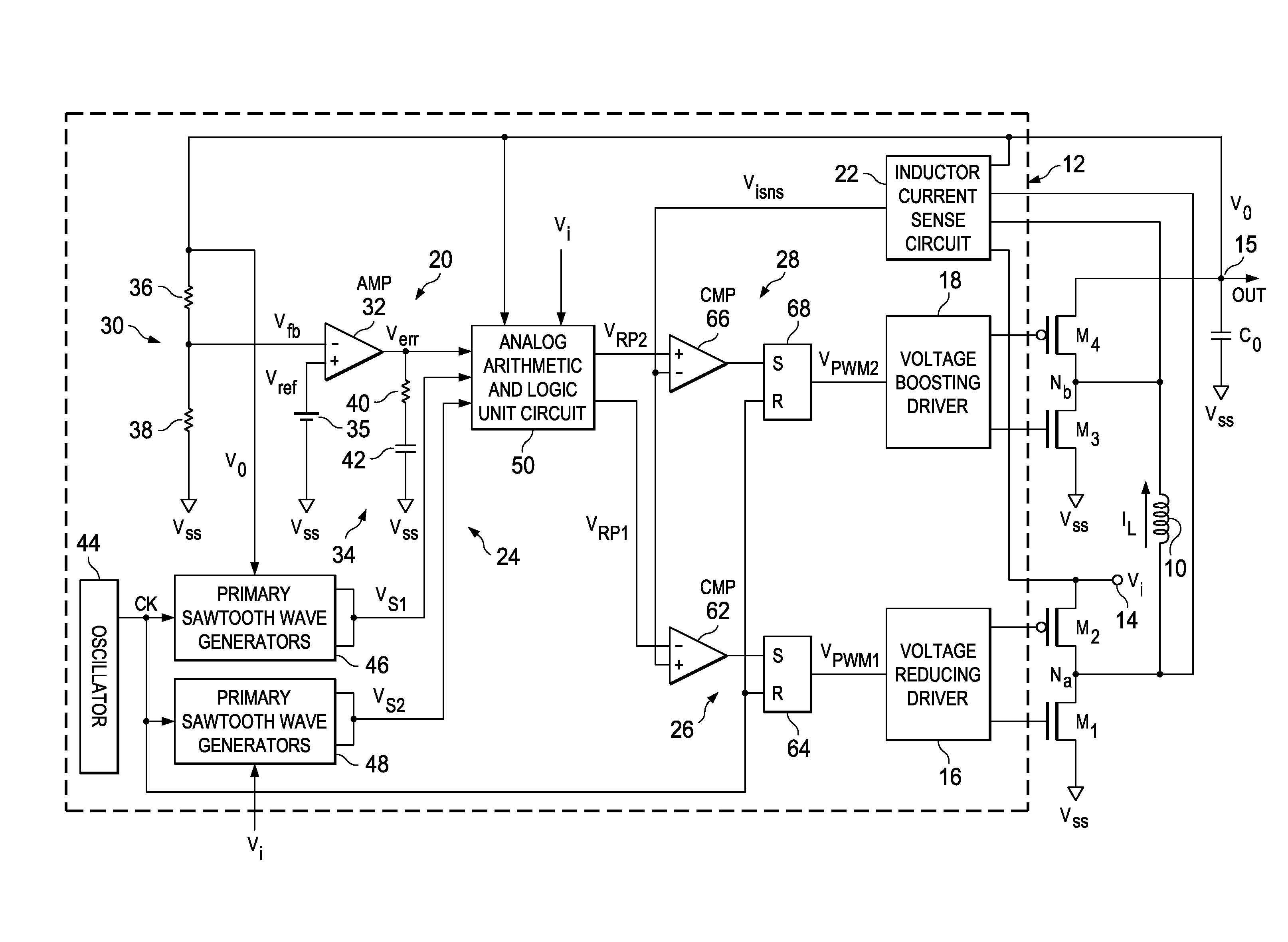
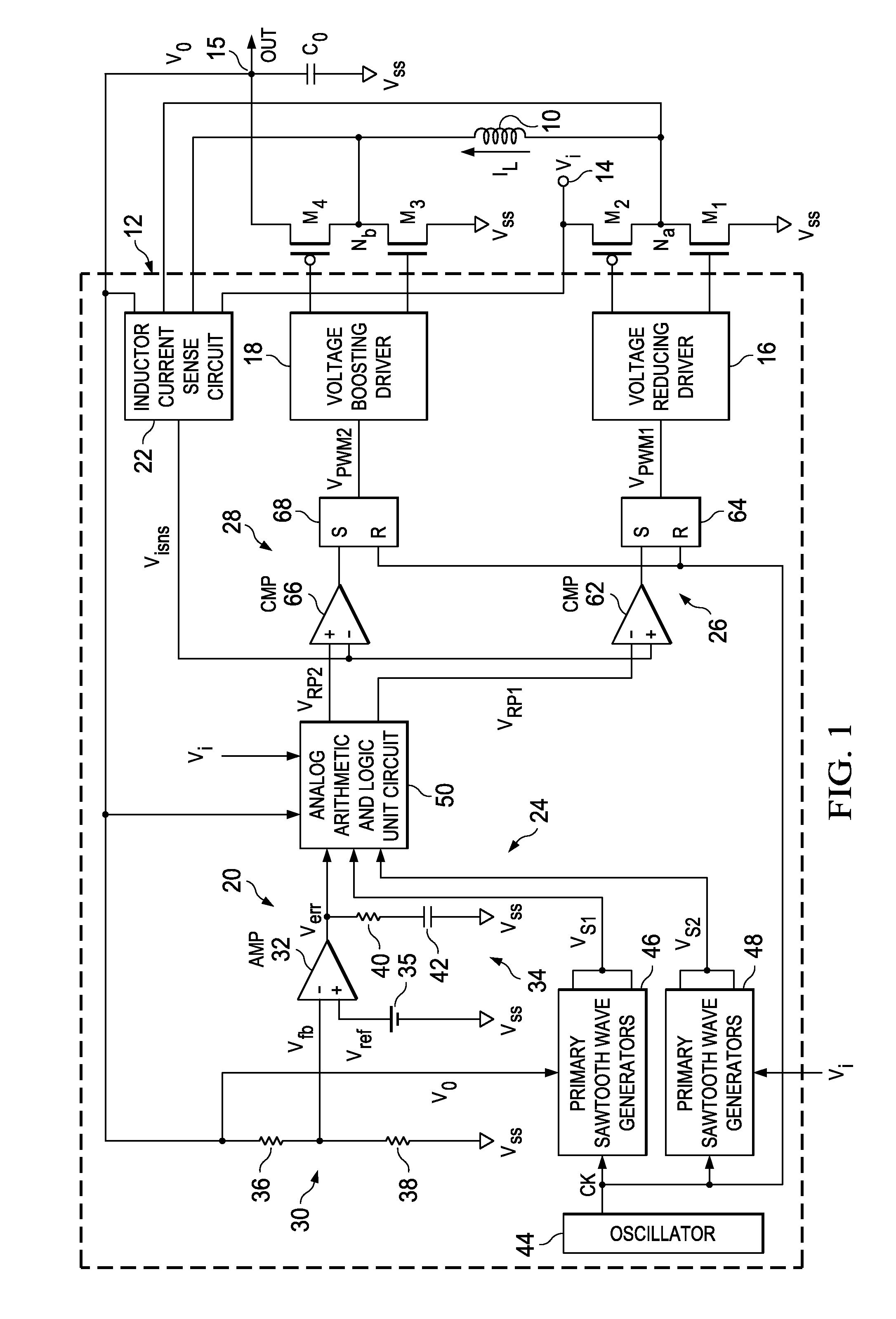
[0051]FIG. 1 is a diagram illustrating the constitution of the circuit of the voltage buck-boost switching regulator in an embodiment of the present invention.

[0052]This voltage buck-boost switching regulator has a pair of voltage reducing transistors M1, M2, a pair of voltage boosting transistors M3, M4, inductance coil 10, output capacitor Co and controller 12.

[0053]More specifically, the two terminals of inductance coil 10 are connected to nodes Na, Nb, respectively. Then, NMOS transistor M1 is connected between reference voltage terminal (Vss) at ground potential and node Na, ...


PUM


Abstract

A stable, high-speed, high-efficiency constant voltage is provided without a complicated, large-scale, high-cost phase compensation circuit over a wide range of operating conditions. This voltage buck-boost switching regulator consists of a pair of voltage reducing transistors, a pair of voltage boosting transistors, inductance coil, output capacitor and controller. The controller has the following parts for performing PWM control of constant voltage for voltage reducing transistors and voltage boosting transistors: an output voltage feedback circuit, an inductor current sense circuit, a variable sawtooth wave signal generator, switching controllers, and a voltage boosting driver.

Description

CROSS-REFERENCE TO RELATED APPLICATIONS[0001]This patent application claims priority from Japanese Patent Application No. 2008-321465, filed Dec. 17, 2008, the entirety which is incorporated herein by reference.FIELD OF THE INVENTION[0002]The present invention pertains to a switching regulator that converts the input DC power (DC) to any DC power (DC). Specifically, the present invention pertains to a voltage buck-boost switching regulator that can provide a constant output voltage independent of the input voltage.BACKGROUND OF THE INVENTION[0003]Switching regulator is a small, lightweight, high-efficiency DC power supply using semiconductor switching elements, and is in wide use in electronic devices, etc. In recent years, the demand for smaller size, lighter weight and higher efficiency has constantly increased. The basic principle of the switching regulator is as follows: the switching elements are turned on / off at a high frequency, and the ratio of the on / off periods, that is, t...

Claims


Application Information

Patent Timeline
Patent Type & Authority Patents(United States)
IPC IPC(8): G05F1/24
CPCH02M3/1582
Inventor SAITOH, MITSUYORI
Owner TEXAS INSTR INC
Why Eureka
Try Eureka