Storage control apparatus and storage control method

a storage control and control apparatus technology, applied in error detection/correction, instruments, computing, etc., can solve problems such as public knowledge, increase the minimum access unit to one chip, and error occuring for a dram

Inactive Publication Date: 2013-05-07
HITACHI LTD
View PDF19 Cites 4 Cited by
  • Summary
  • Abstract
  • Description
  • Claims
  • Application Information

AI Technical Summary

Benefits of technology

[0013]Consequently, an object of the present invention is to improve at least two trade-offs of a performance, a reliability, and availability for a storage control apparatus.Solution of Problem

Problems solved by technology

On the other hand, it is publicly known that an error occurs for a DRAM.
The error is that a minimum access unit to one chip is increased, the number of chips that can be read or written at one time is decreased, and incorrect data is stored for instance.

Method used


Image

  • Storage control apparatus and storage control method
  • Storage control apparatus and storage control method
  • Storage control apparatus and storage control method

Examples


embodiment 1

[0040]In accordance with the present embodiment, the availability of a whole of a storage system can be maintained, and the reliability and a performance of a storage system can be achieved at the same time. A first embodiment of the present invention will be described below in detail with reference to the drawings.

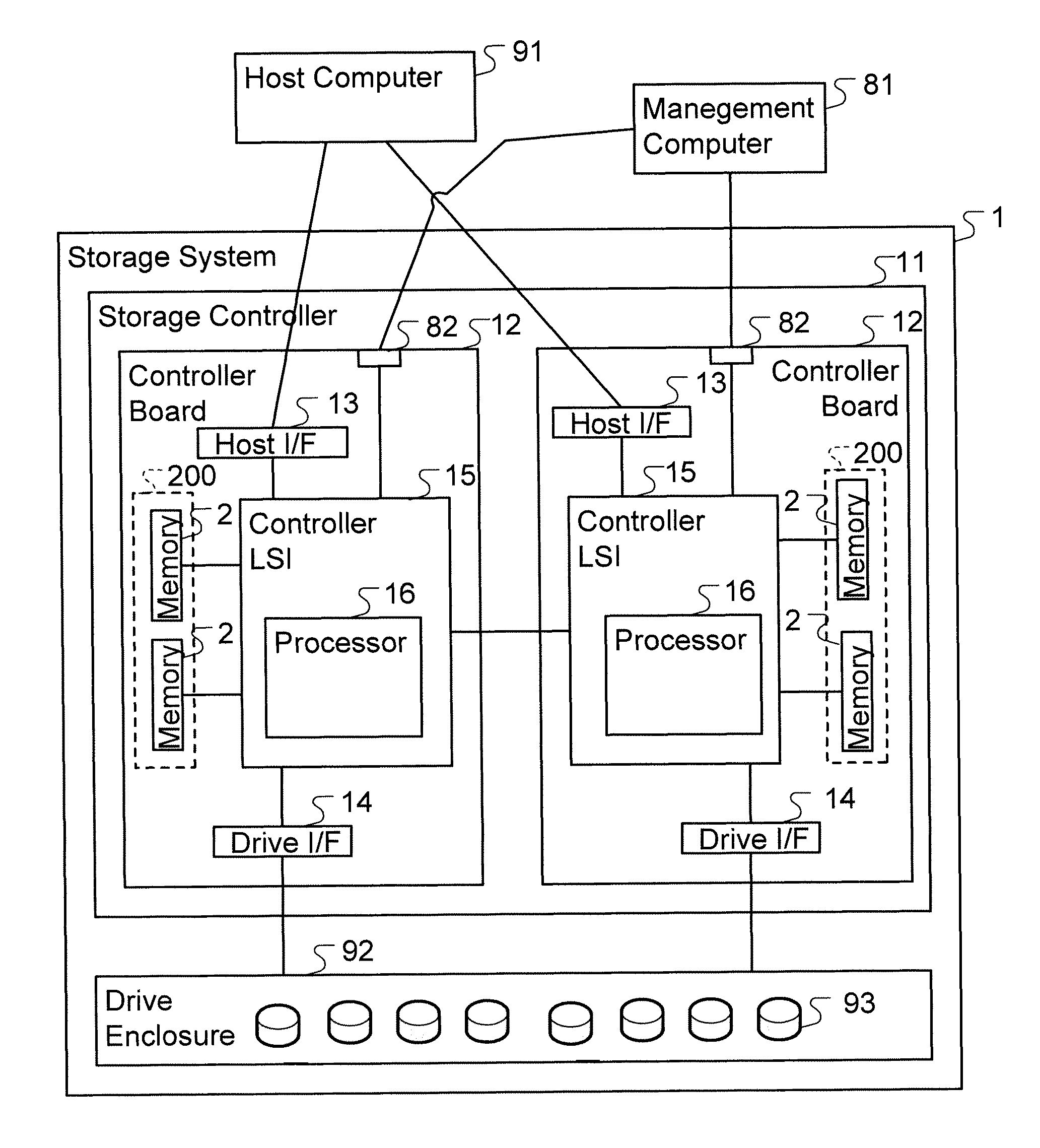
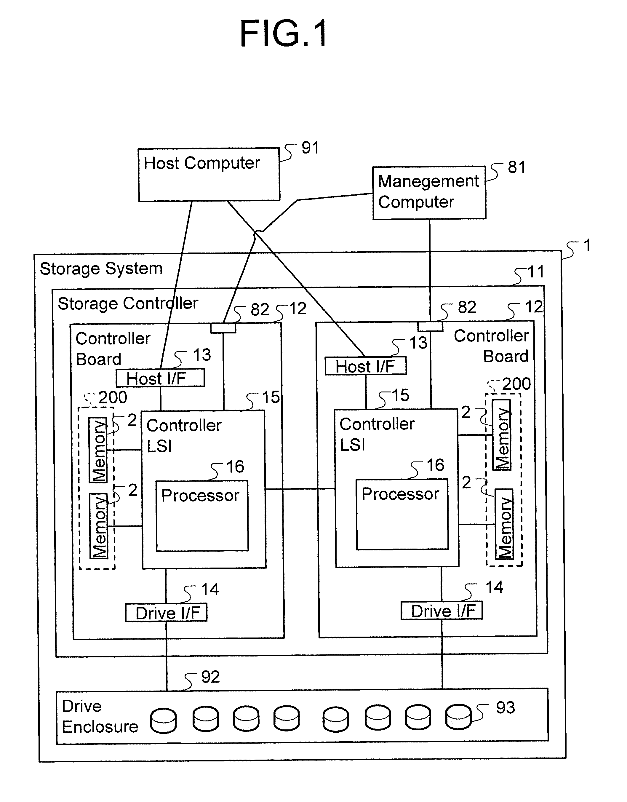
[0041]FIG. 1 is a view showing an example of a computer system that is provided with a storage system in accordance with a first embodiment of the present invention.

[0042]The computer system is provided with a host computer 91, a management computer 81, and a storage system 1.

[0043]The host computer 91 is a computer that is provided with a function that issues an I / O (Input / Output) command for reading or writing data for the storage system 1. The host computer 91 is coupled to the storage system 1 by a host interface 13.

[0044]The management computer 81 is a computer that is provided with a function that manages a status of the storage system 1. The management computer 81 ...

embodiment 2

[0156]In accordance with the present embodiment, while the performance of the storage system 1 is maintained, and the reliability and the availability of the storage system 1 can be achieved at the same time. For the present embodiment, a difference from the first embodiment will be described below in detail with reference to the drawings.

[0157]FIG. 13 is a view showing an example of a configuration of a memory module group 200 in accordance with a second embodiment of the present invention.

[0158]For the present embodiment, the memory module group 200 is also divided into groups of two types on the controller board 12. One group is an ECC group 53 in a high availability mode (hereafter referred to as a high availability ECC group), and the other group is an ECC group 54 in a high reliability mode (hereafter referred to as a high reliability ECC group). The high availability ECC group 53 stores the user data 311. The high reliability ECC group 54 stores the control data (such as the ...

embodiment 3

[0182]In accordance with the present embodiment, while the reliability and the performance of the storage system 1 is maintained, and the availability of the storage system 1 can be achieved at the same time. For the present embodiment, a difference from the first embodiment will be described below in detail with reference to the drawings.

[0183]FIG. 16 is a view showing an example of a configuration of a memory module group 200 in accordance with a third embodiment of the present invention.

[0184]For the present embodiment, the memory module group 200 is also divided into groups of two types on the controller board 12. One group is an ECC group 55 in a high capacity mode (hereafter referred to as a high capacity ECC group), and the other group is an ECC group 56 in a high reliability high availability mode (hereafter referred to as a high reliability high availability ECC group). The high capacity ECC group 55 stores the user data 311. The high reliability high availability ECC group...


PUM


Abstract

Memory module groups are provided which include a memory module, which includes memory chips. In the case in which an error chip that is a memory chip that is provided with an error is in a first memory module, a first memory module group that is provided with the error chip is not managed as a memory module group that cannot be used even if an error of the first data element is mis-corrected based on the error detecting code of the first kind. In the case in which an error chip is in a second memory module, a second memory module group that is provided with the error chip is not managed as a memory module group that cannot be used in such a manner that an error of the second data element is not mis-corrected based on the error detecting code of the second kind.

Description

TECHNICAL FIELD[0001]The present invention relates to a storage control apparatus that is configured to store data into a memory in accordance with an access command that is transmitted from a host computer.BACKGROUND ART[0002]A storage system that is configured by a plurality of physical storage devices (such as an HDD (Hard Disk Drive) and a flash memory device) is known publicly. As a storage system, there can be known publicly for instance a system that is provided with a cache memory that stores data that can be read and written in addition to a simple read and write function, a redundant controller system, and a system that is provided with a snapshot function that carries out a duplication of a volume in little time.[0003]Such a storage system is provided with a wide variety of functions as described above. In recent years, such a storage system has been provided with a memory with a large capacity, a DRAM (Dynamic Random Access Memory) in a quintessential way in order to imp...

Claims


Application Information

Patent Timeline
Patent Type & Authority Patents(United States)
IPC IPC(8): G11C29/00
CPCG06F11/2089G06F11/108G06F12/0802G06F2211/1035
Inventor TAKADA, MASANORI
Owner HITACHI LTD
Why Eureka
Try Eureka