Method and apparatus for storing information using an intelligent block storage controller
a technology of intelligent block storage and storage controller, which is applied in the direction of error detection/correction, input/output to record carriers, instruments, etc., can solve the problems of reducing the number of lifetime program/erase cycles, reducing the feature size, and creating many challenges, so as to reduce warranty costs, reduce failure rates, and increase the lifetime of storage drives
- Summary
- Abstract
- Description
- Claims
- Application Information
AI Technical Summary
Benefits of technology
Problems solved by technology
Method used
Image
Examples
example 1
ure
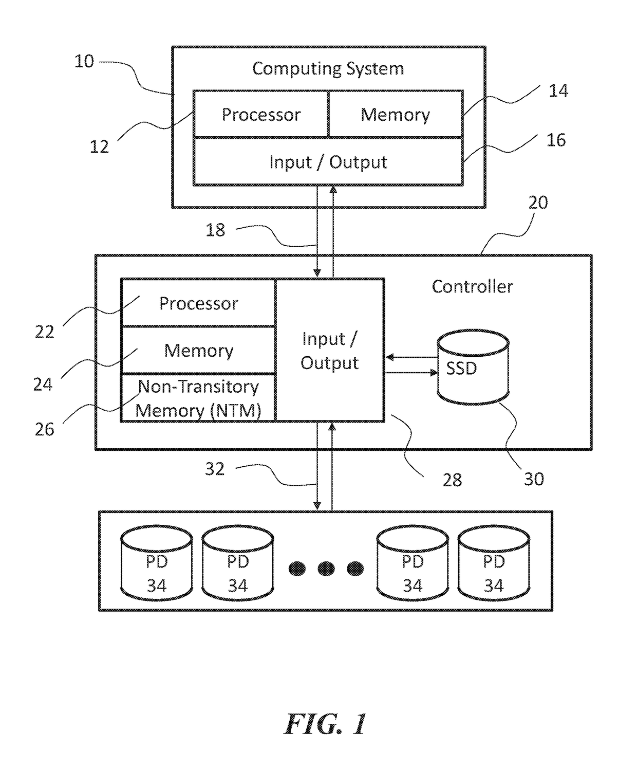
[0088]FIG. 1 shows an example diagram of a computing system connected to an example storage controller and physical storage drives. There is a computing system 10 with processors 12, memory 14, and an Input / Output (I / O) subsystem 16 allowing the computing system 10 to interface with many devices, including storage devices. In this example, the Input / Output subsystem 16 using a SAS interconnect 18 to interface with a controller 20 disclosed herein. The controller 20 has one or more processors 22, volatile memory 24, and Non-Transitory Memory (NTM) 26, and its own I / O subsystem 28.
[0089]The controller 20 also incorporates a private internal storage 30 (e.g., a solid-state drive) and additional private SAS interconnects 32 used to interface with one or more physical drives (PDs) 34.
[0090]The controller implementation shown in FIG. 1 is only one of many possibilities. Any storage interconnect technology such as SATA, Fibre Channel, or iSCSI is suitable for either the SAS interconnect...
example 2
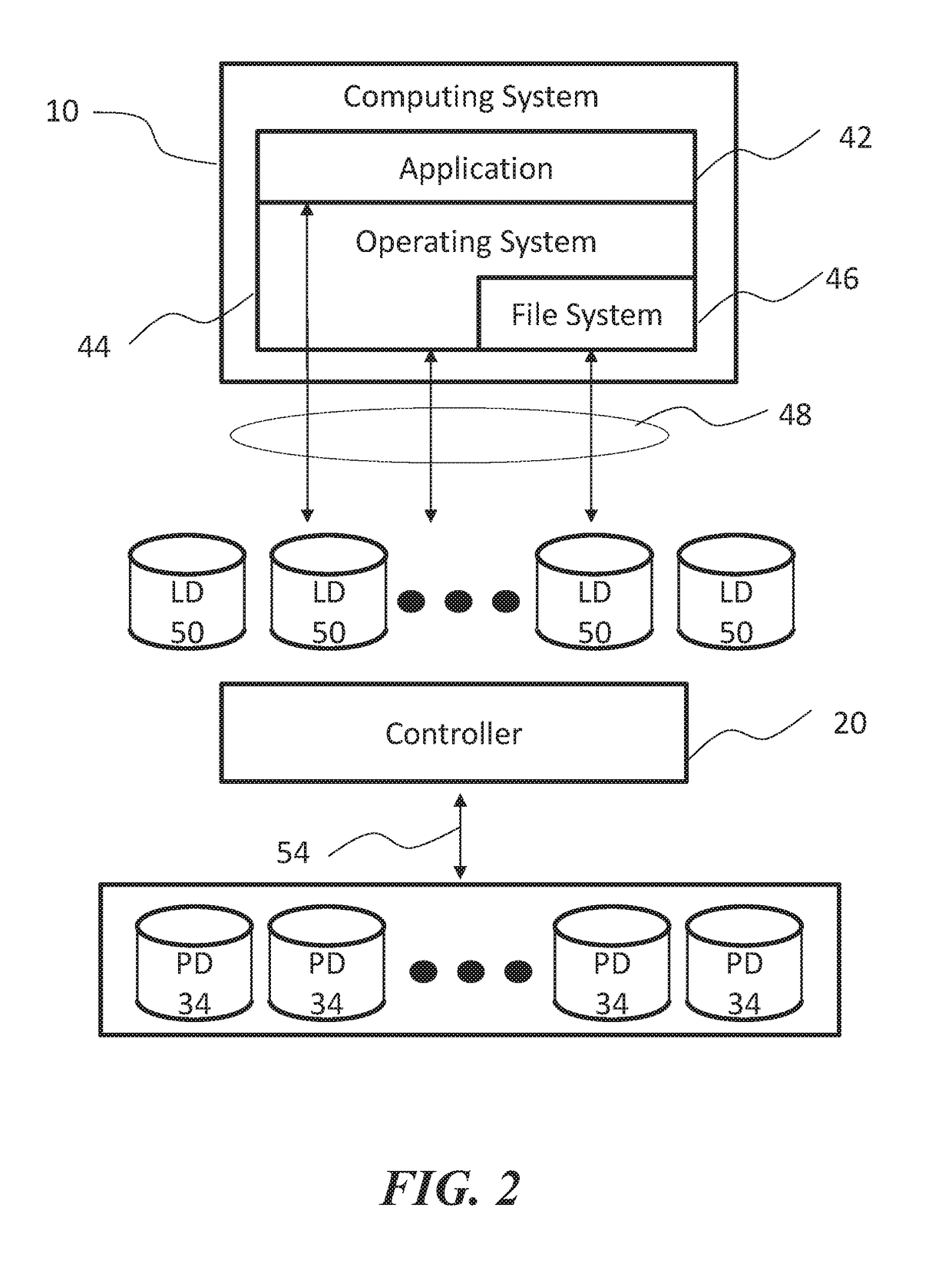
[0094]FIG. 2 illustrates a computing system 10, running software applications 42 on an operating system 44. The operating system 44 contains a file system 46. In some embodiments, the applications 42, operating system 44 and file system 46 all use block storage accesses 48 to utilize the logical storage drives 50.
[0095]The logical storage drives (LD) 50 are logical entities composed by the controller 20 from one or more PDs 34, which the controller 20 accesses using block storage accesses 54.
[0096]In some embodiments, logical storage drives 50 are individually identified by a unique logical unit number (e.g., 1, 2, 3, etc.).
[0097]The applications 42, operating system 44, and file system 46 cannot utilize the PDs 34 directly. The block storage accesses 48 of the applications 42, operating system 44, and file system 46 to the LDs 50 are transformed by the controller 20, resulting in a different set of block storage access 54 to the PDs 34.
[0098]Support for a large number of logical st...
example 3
e Write: Overview
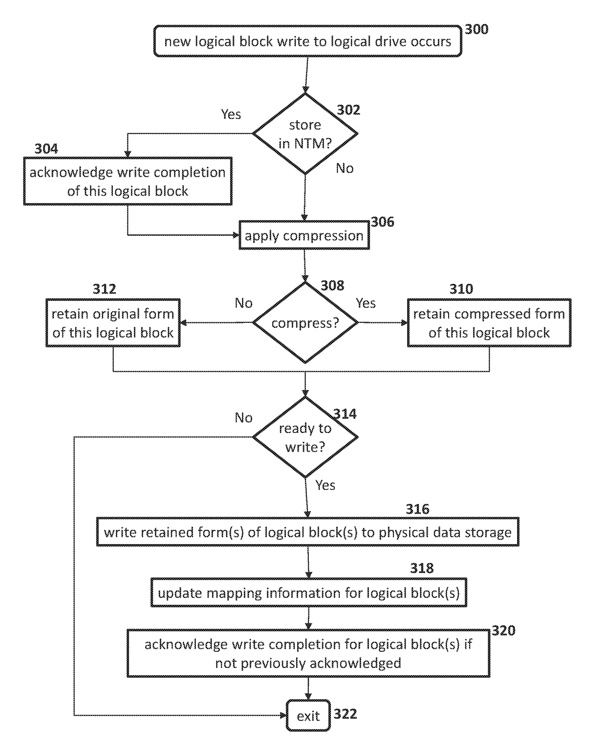
[0107]FIG. 3A shows an overview of a data write process. As in 300, a computing system requests to write data to a logical block within the logical drive. When the controller receives the write request, its operation 302 decides whether or not to store data in a NTM. If there is a NTM present and if the NTM has available space, the operation 302 takes the “Yes” path; the step 304 acknowledges write completion of the logical block, followed by applying a compression algorithm 306. At the check 302, if there is no NTM or the NTM is full, the controller takes the “No” path, where the controller directly applies a compression algorithm 306.
[0108]In some cases, the controller performs a check 308 to determine if the data has been compressed. If compressed, the operation 310 retains the compressed form of this logical block; otherwise, the operation 312 retains the original form of this logical block.
[0109]In some cases, a check 314 is made to determine if the controller ...
PUM
 Abstract
Description
Claims
Application Information
 - R&D
- Intellectual Property
- Life Sciences
- Materials
- Tech Scout
- Unparalleled Data Quality
- Higher Quality Content
- 60% Fewer Hallucinations
Browse by: Latest US Patents, China's latest patents, Technical Efficacy Thesaurus, Application Domain, Technology Topic, Popular Technical Reports.
© 2025 PatSnap. All rights reserved.Legal|Privacy policy|Modern Slavery Act Transparency Statement|Sitemap|About US| Contact US: help@patsnap.com


