
Chemical Mechanical Planarization Slurry Composition Comprising Composite Particles, Process for Removing Material Using Said Composition, CMP Polishing Pad and Process for Preparing Said Composition

Active Publication Date: 2016-03-31
CABOT CORP
View PDF1 Cites 5 Cited by
  • Summary
  • Abstract
  • Description
  • Claims
  • Application Information

AI Technical Summary

Benefits of technology

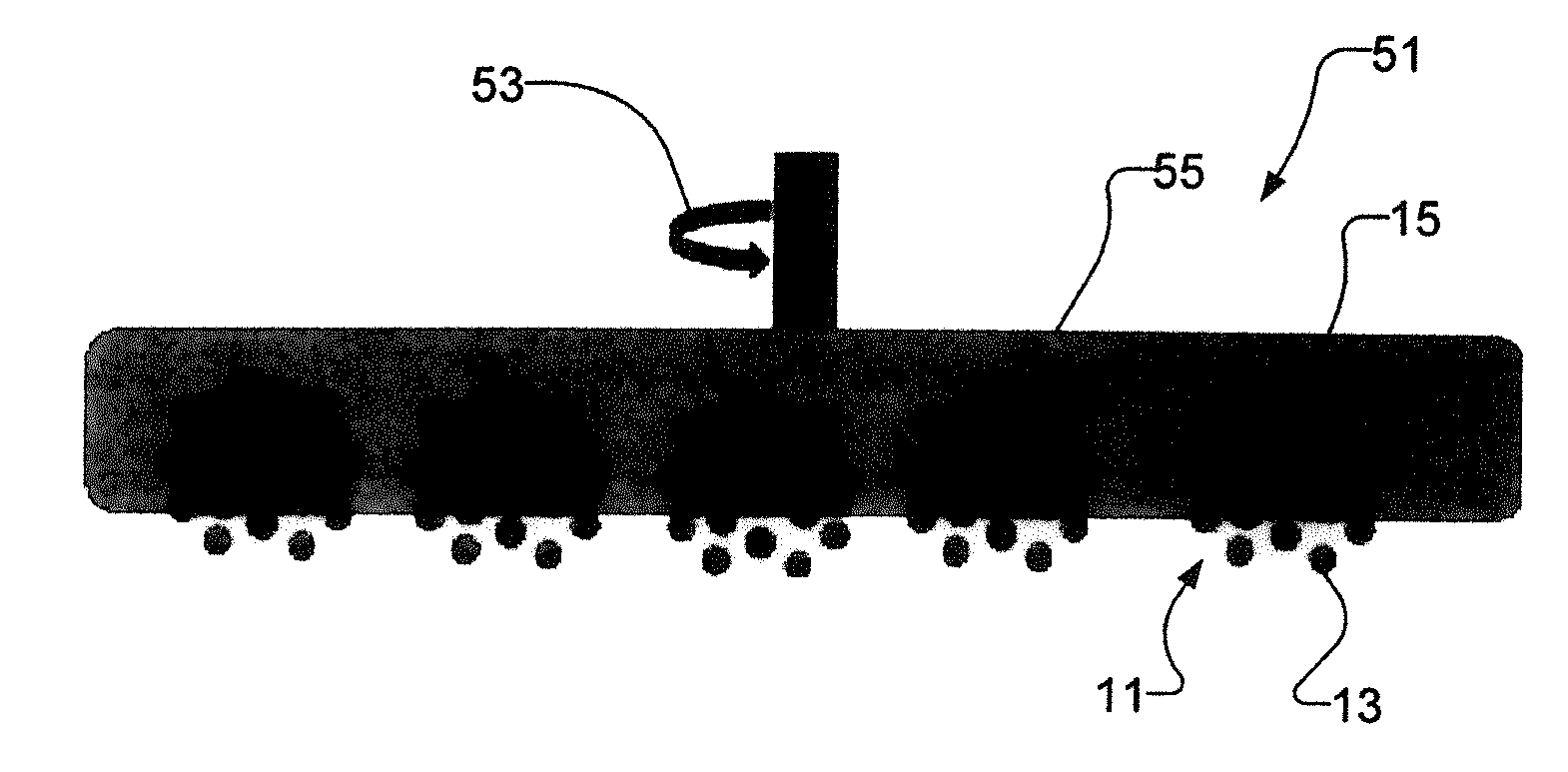
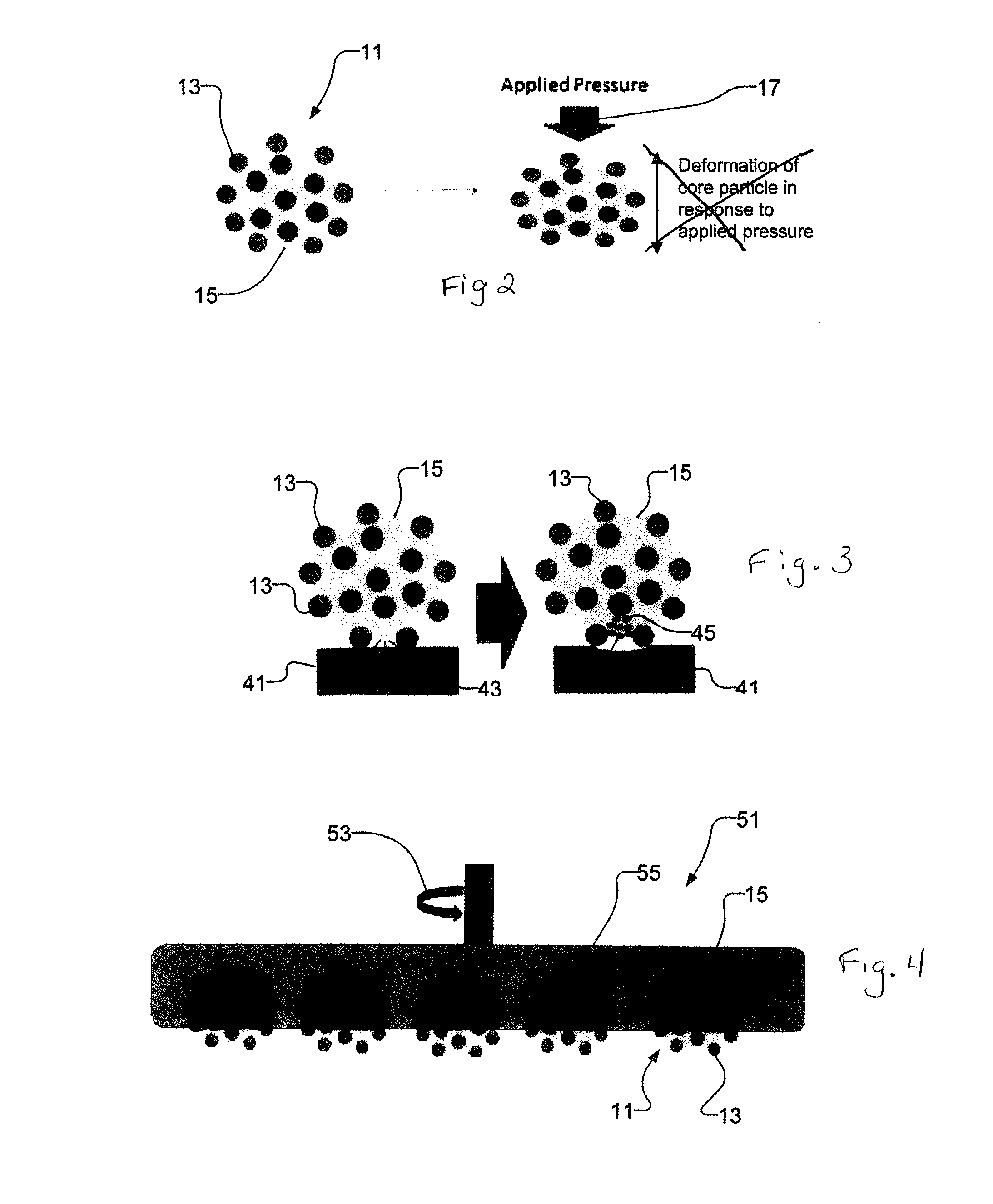
The patent describes a new way to create particles that combine the benefits of small and large particles, as well as softer and harder materials. These composite particles can be used to improve the performance of slurries used in polishing processes, reducing defects and improving performance. The particles also have reduced defectivity and can be easily removed during post-polishing cleaning. Inorganic materials can be added to the particles to improve their hardness, removal rate, or selectivity, and there may be benefits in reducing the mass loadings of the particles. Overall, the use of composite particles can improve the efficiency and effectiveness of polishing processes.

Problems solved by technology

Since defective workpieces often need to be re-processed or discarded, their occurrence has a major impact on the costs and efficiency of the overall manufacturing process.
With use, the working surface of the pad can become eroded.
Polishing debris can get trapped in the surface micro-channels, clogging them.
However, defectivity (often expressed as the number of scratches) also increases with particle size and can reduce device yield by ultimately causing chip failures that are not detected until fabrication is completed.
Smaller particles, however, are also more difficult to detect during post CMP metrology steps (e.g. defectivity measurements), and they are more difficult to remove by cleaning operations that follow CMP.
These residual particles pose the threat of greater defectivity and lost yield, as subsequently deposited layers in the IC architecture trap the defect residual particle, which can ultimately cause performance issues in the final product.

Method used


Image

  • Chemical Mechanical Planarization Slurry Composition Comprising Composite Particles, Process for Removing Material Using Said Composition, CMP Polishing Pad and Process for Preparing Said Composition
  • Chemical Mechanical Planarization Slurry Composition Comprising Composite Particles, Process for Removing Material Using Said Composition, CMP Polishing Pad and Process for Preparing Said Composition
  • Chemical Mechanical Planarization Slurry Composition Comprising Composite Particles, Process for Removing Material Using Said Composition, CMP Polishing Pad and Process for Preparing Said Composition

Examples


example 1

[0132]This example demonstrates the preparation of a polyester latex in accordance with an embodiment of the invention.

[0133]To a 500 mL round bottom flask with overhead stirrer and thermocouple was added 50 g polyester resin (Reichold Fine-tone T-6694 resin, acid number 13 mg KOH / g resin, Tg=50-60° C.), 25 g methyl ethyl ketone, and 6.25 g isopropyl alcohol. The mixture was stirred at 250 rpm and maintained at 45° C. for 3 hours, after which 2.17 g 10% ammonium hydroxide solution (13.6 mmol) was added slowly. The mixture was stirred for a further five minutes, after which 5 g methacryloxypropyl-trimethoxysilane (MPS) was added. This mixture was stirred for 10 minutes, after which 150 g deionized water was slowly added to produce a dispersion. The mixture was heated to 95-98° C. and about 40 g liquid was distilled off. The heating mantle was removed and the reaction mixture cooled to room temperature.

example 2

[0134]This example demonstrates the formation of organosilica-polyester composite particles in accordance with an embodiment of the invention.

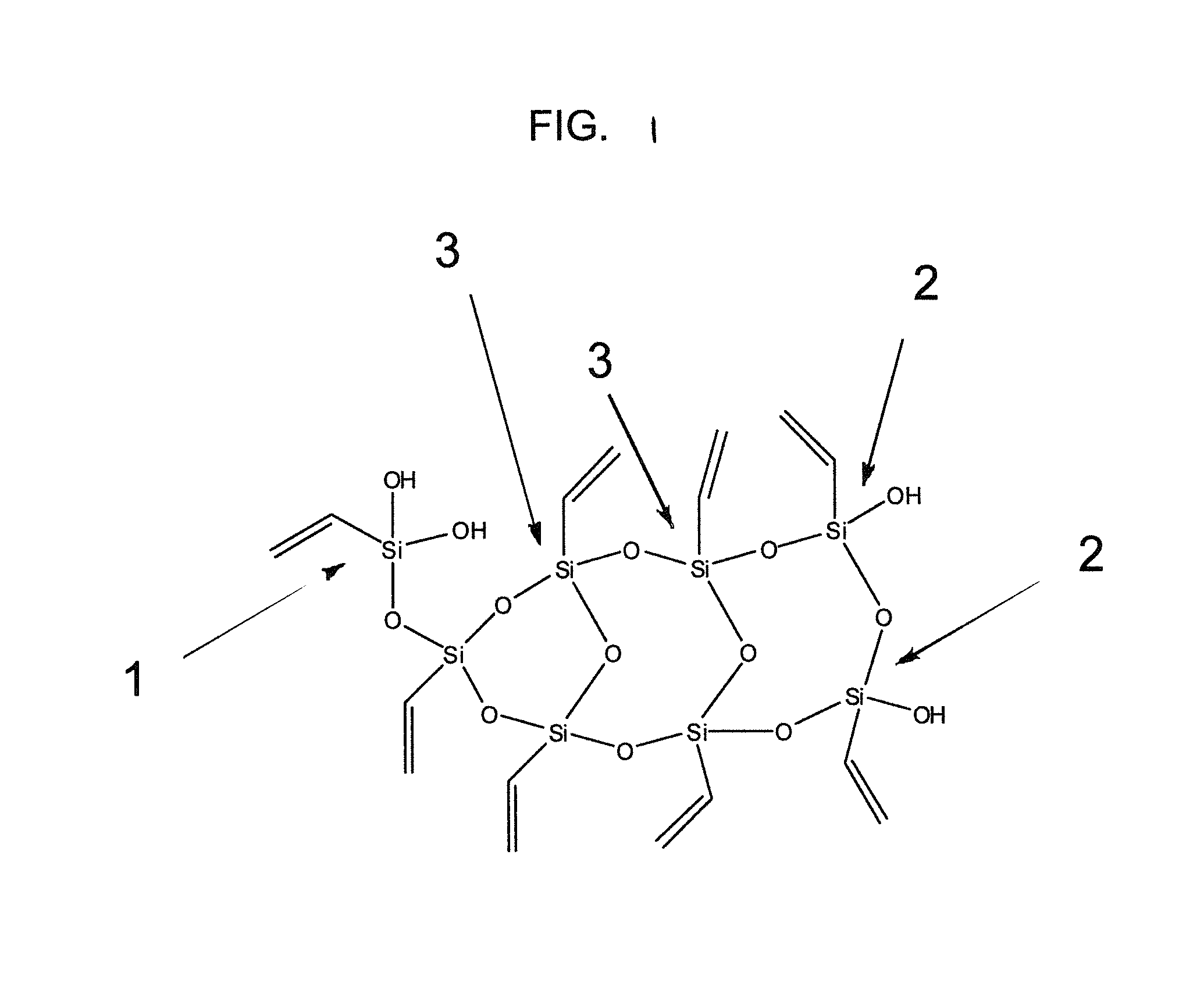
[0135]38 g of the latex from Example 1 (26.4 wt % polyester+MPS) was diluted with 162 g deionized water to form a 5 wt % dispersion. 5 g of vinyltrimethoxysilane (VTMS, MW 148, 34 mmol) was dissolved in 25 g deionized water and stirred with a magnetic stir bar (300 rpm) for ˜60 min until the organic droplets were completely dissolved and a transparent solution was obtained. 1 g of 30% ammonium hydroxide solution (MW=34) was added to the diluted latex dispersion and mechanically stirred for 5 min. The VTMS solution was added over one minute and the reaction allowed to proceed for 3 hours at room temperature. A second solution of VTMS, identical to the first, was prepared and added to the reaction mixture, and the reaction was allowed to proceed for an additional 3 hours. Transmission electron microscopy of the resulting particle dispersion is s...

example 3

[0136]This example demonstrates formation of organosilica-polyester composite particles in accordance with an embodiment of the invention.

[0137]The latex of Example 1 was prepared without addition of MPS to the polymer / solvent solution. Rather, 1 g of MPS was added to 40 g of the latex (about 25 wt % polymer) and stirred for 2 hours until the MPS droplets disappeared. Then, 160 g deionized water was added to dilute the dispersion to 5 wt % polymer. A VTMS solution was prepared as in Example 2. 1 g of 30% ammonium hydroxide solution (MW=34) was added to the diluted latex dispersion and mechanically stirred for 5 min. The VTMS solution was added over one minute and the reaction allowed to proceed for 3 hours at room temperature. A second solution of VTMS, identical to the first, was prepared and added to the reaction mixture, and the reaction was allowed to proceed for an additional 5 hours. The resulting composite particles were recovered by evaporation of the solvent at room tempera...


PUM


Abstract

CMP processes, tools and slurries utilize composite particles that include core particles having organosilica particles disposed about the core particles. Using these processes, tools and slurries can enhance removal rates, reduce defectivity and increase cleanability with respect to comparable systems and substrates.

Description

CROSS-REFERENCE TO RELATED APPLICATIONS[0001]This patent application claims the benefit of U.S. Provisional Patent Application 61 / 819,229, filed on May 3, 2013, U.S. Provisional Patent Application 61 / 919,215, filed on Dec. 20, 2013, and U.S. Provisional Patent Application No. 61 / 919,251, filed on Dec. 20, 2013, and PCT Application No. PCT / US2014 / 031078, filed on Mar. 18, 2014, the entire contents of all of which are incorporated herein by reference.BACKGROUND OF THE INVENTION[0002]Mixed phase particles including an organic phase and an inorganic phase have found utility in a wide variety of applications. When such particles are themselves used in polymer composites, it is desirable that they include surface roughness to enhance their interaction with the surrounding matrix and that their polymer cores be able to mitigate crack propagation. For example, it may be desirable that the organic core be soft (e.g., a polymer with a low glass transition temperature) or resilient. Alternativ...

Claims


Application Information

Patent Timeline
IPC IPC(8): C09G1/02B24B37/04
CPCB24B37/044C09G1/02C09K3/1409C09K3/1463
Inventor ZHANG, QINGLINGGREENWOOD, BENNETTSHARMA, RAVIMOESER, GEOFFREY, D.PREVO, BRIAN, G.HAMPDEN-SMITH, MARK, J.
Owner CABOT CORP
Learn More