
Electrical regenerative braking

a technology of regenerative braking and electric motor, which is applied in the direction of electric generator control, motor/generator/converter stopper, dynamo-electric converter control, etc., can solve the problems of increasing the load of in-car electronics, and the current solution of regenerative braking is not effective if used at lower speeds, so as to achieve low speed, energy saving, and additional energy saving

Inactive Publication Date: 2013-05-14
NXP BV
View PDF11 Cites 1 Cited by
  • Summary
  • Abstract
  • Description
  • Claims
  • Application Information

AI Technical Summary

Benefits of technology

The invention is an electric regenerative braking system that can save energy and reduce wear and tear on conventional brakes in vehicles. It can also be used in hybrid vehicles to save energy and reduce emissions. The system uses additional coils that can be switched on and off to regulate the magnetic field. The coils can be pulsed and controlled by a regenerative circuit. Essentially, this patent describes a single electromagnetic system that relies on the same coil to produce an induction current for braking.

Problems solved by technology

Such energy savings have become important due to increasing fuel costs and stringent automobile emission norms.
Added to this is the increasing load of in-car electronics.
Due to this reason the current solutions for regenerative braking are not effective if used at lower speeds.

Method used


Image

  • Electrical regenerative braking
  • Electrical regenerative braking
  • Electrical regenerative braking

Examples


Embodiment Construction

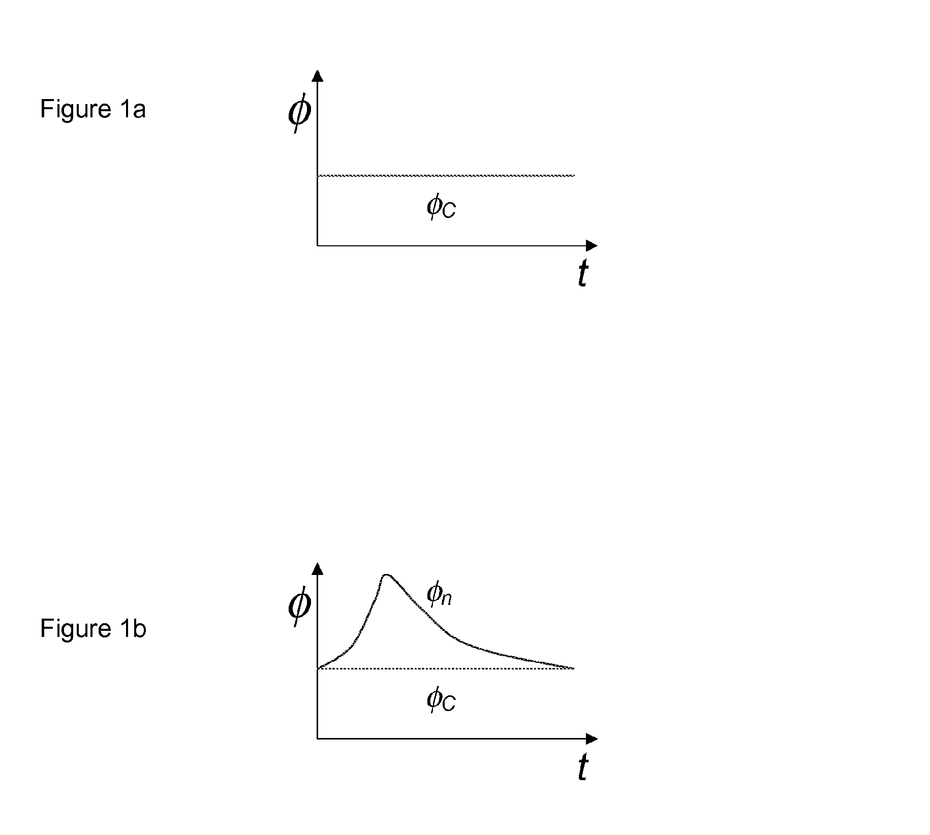
[0031]It may be observed that the magnetic field øc existing across the coils remains constant with time. This can be represented by the plot in FIG. 1a. Due to this reason the regenerative braking according to the state of the art is not effective it used at lower speeds. Also the energy savings obtained are suboptimal.

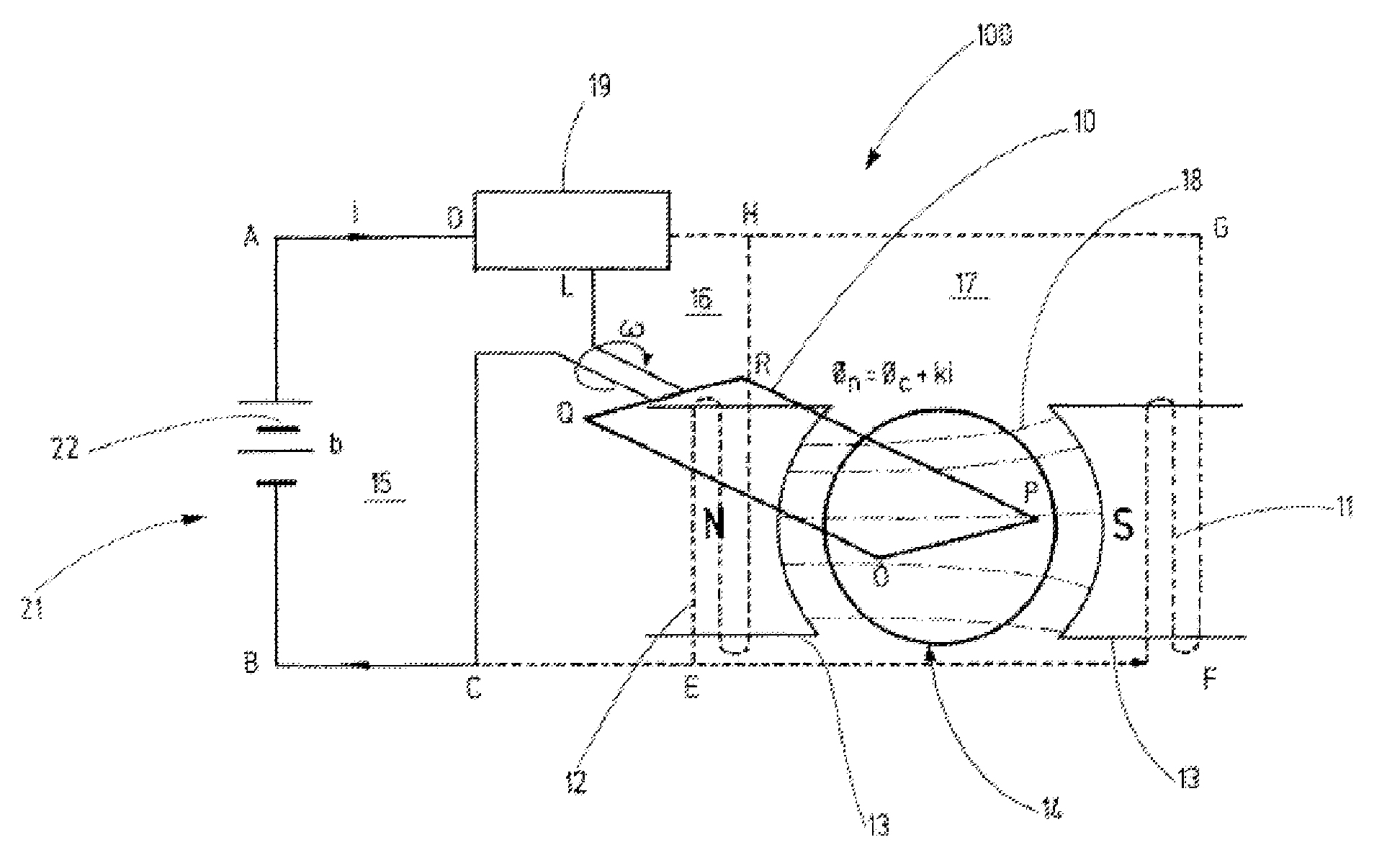
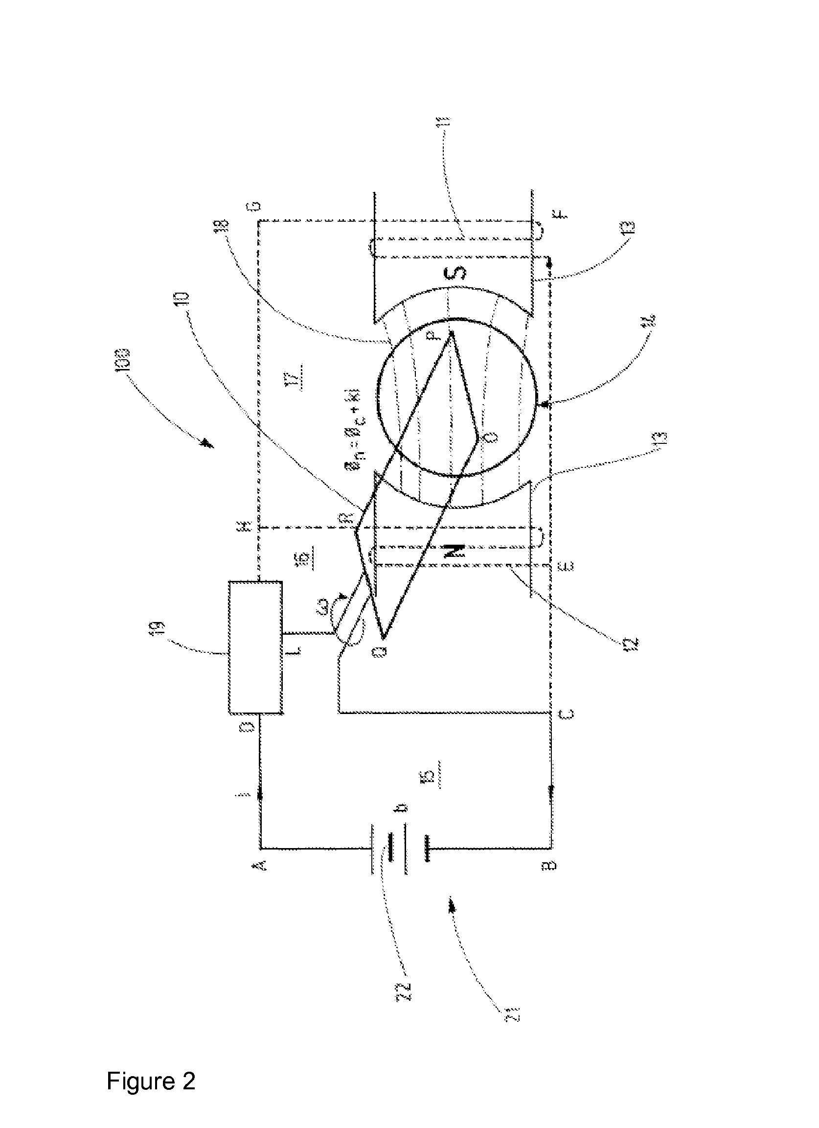
[0032]To overcome these drawbacks of regenerative braking according to the state of the art, additional coils 11, 12 are placed around the permanent magnet 13 of the electrical regenerative braking 100 shown in FIG. 2. The braking 100 has an electric circuit 22 which contains the rotating brake coil 10 and the additional coils 11, 12 as elements.

[0033]According to Faraday's law an emf (Electro-motive force) is generated by the rotating brake coil 10, which is attached to a wheel 14 of the vehicle, due to the magnetic field øc of the permanent magnet 13. The magnetic field øc has the reference number 18. When the brakes are applied, assume that the points D and L beco...


PUM


Abstract

This invention relates to an electrical regenerative brake (100) with a rotating brake coil (10) which is mounted on a wheel (14) of a vehicle, whereby a magnetic field (18) is fed in the coil (10). In order to allow effective regenerative braking (100) at low speeds and to provide a significant increase in power saving, this invention proposes that the permanent magnet (13) producing the magnetic field (18) is placed in the inner space of at least one additional coil (11, 12), whereby the brake has an electric circuit (22) which contains the rotating brake coil (10) and the additional coil (11, 12) as elements.

Description

FIELD OF INVENTION[0001]The present invention relates to an electrical regenerative braking with a rotating brake coil which is mounted on a wheel of a vehicle, whereby a magnetic field is fed in the coil.[0002]The present invention further relates to a method according to the preamble of claim 10.BACKGROUND OF THE INVENTION[0003]Electrical regenerative brakes are an essential component in all modem electric and hybrid vehicles. During regenerative braking the kinetic energy of the vehicle is converted into electrical energy and stored for future use. Such energy savings have become important due to increasing fuel costs and stringent automobile emission norms. Added to this is the increasing load of in-car electronics. HVAC (Heating, Ventilation and Air-Conditioning), infotainment devices, and safety & comfort systems contribute towards the majority of the electrical power consumption in cars. Regenerative braking is always used in combination with conventional braking systems.[000...

Claims


Application Information

Patent Timeline
Patent Type & Authority Patents(United States)
IPC IPC(8): H02P3/18
CPCH02P3/14B60L2220/44H02P2101/45Y02T10/642Y02T10/64
Inventor LAHIRI, ANIRBAN
Owner NXP BV
Learn More