Bidirectional hysteretic power converter

a power converter and hysteretic technology, applied in the direction of electric variable regulation, process and machine control, instruments, etc., can solve the problems of buck converter control quite different from the control of buck converter, rhpz can complicate the stability of the loop, and the overall response of the boost converter is quite slow, so as to reduce the value, size and cost of its passive components

Active Publication Date: 2013-05-14
QUALCOMM INC
View PDF10 Cites 11 Cited by
  • Summary
  • Abstract
  • Description
  • Claims
  • Application Information

AI Technical Summary

Benefits of technology

[0022]It is an objective of the present invention to provide an hysteretic bidirectional switching power converter that can operate in both directions at high switching frequency therefore allowing a reduction of the value, size, and cost of its passive components. In one direction the converter would operate as a buck converter and in the opposite direction it would operate as a boost converter, utilizing the same power devices, the same inductor and possibly the same or similar control methods.
[0023]It is another objective of the present invention to provide a switching bidirectional power converter that includes an hysteretic or pseudo-hysteretic control circuit by means of one or more feedback networks that generate signals deriving from the information of the instantaneous output voltage, both from a dc standpoint and from an ac standpoint, and a means of generating one or two synthetic ripple signals that are proportional and in phase with the inductor current allowing very fast load transient response when operating as a boost converter.
[0024]It is another objective of the present invention to provide a switching bidirectional converter with high efficiency at any load condition by means of control in CCM (Continuous Conduction Mode) mode of operation and DCM (Discontinuous Conduction Mode) mode of operation depending on the load impedance values.
[0035]The topology and values of the components in the feedback network define the self oscillating switching frequency, the stability, and the load and line transient response performance of the converter. The switching frequency has a direct impact on the output voltage ripple and on the converter efficiency. The switching frequency can be regulated and imposed by a separate frequency control loop that can be implemented in various ways. When the switching frequency is regulated, for example by means of a PLL (Phase Lock Loop), the study of the loop becomes more complex and an accurate analysis can be performed by periodic state analysis to guarantee the circuit stability in all conditions.
[0043]When the battery voltage approaches the desired final charge voltage the charger gradually changes mode of operation into the constant voltage mode and the ramp signal generated by the voltage feedback network 15 starts toggling the hysteretic comparator 21. If the digital levels of the outputs of the comparators 19 and 21 are chosen appropriately, the NAND gate 22 selects the signal to drive the control logic and drivers block 23, so that the transition between the constant current and constant voltage modes is gradual and smooth.
[0047]The inductor charging phase can then be kept active for a predetermined amount of time seeking the optimum trade-off between the switching frequency and the output voltage ripple with the purpose of maximizing the overall converter efficiency. This mode is the DCM mode of operation and it is characterized by a lower switching frequency. The lower the switching frequency, the higher the output voltage ripple for a given inductor and output capacitor value. At light loads it may be desirable to allow higher output voltage ripple in order to obtain higher efficiency. The DCM mode can also be properly adjusted by choosing adequately the values of the components in the feedback network, since automatically, lighter loads command longer time for the output voltage to drop and for the synthetic ripple signal to toggle.

Problems solved by technology

However the control of a buck converter is quite different from the one for the boost converter because the inherent mode of operation is very dissimilar.
This RHPZ can complicate the stability of the loop and generally is dealt with by rolling off the loop gain of the switching voltage regulator at relatively low frequency, making the overall response of the boost converter quite slow.
However this last example, as all the other cited prior art, does not implement the switching power converter with hysteretic control, limiting the use of these power converters only at relatively low operating frequencies In fact Walter et al specifically described the possible control methods clearly omitting the hysteretic or pseudo hysteretic approach due to the intrinsic difficulties in implementing hysteretic control loops, in particular for boost converters.
However, as mentioned, these types of control methods do not present high bandwidth and require the adoption of large output capacitors to obtain acceptable load transient responses.
Fast control of boost converters is difficult to obtain in CCM because there is always an intrinsic delay in providing energy to the load since the inductor has to be first charged with current flowing in it.
The intrinsic delay of the boost architecture, deriving from the fact that the boost does not supply current to the load while charging the inductor, makes the implementation of an hysteretic approach much more difficult to obtain.
However several challenges have to be overcome.
The hysteretic approach of constant current mode at constant switching frequency presents its challenges and the applicants are not aware of any such implementation by third parties.
Here the main challenge is to operate with a pseudo hysteretic approach because the battery acts like a large output capacitor complicating significantly the stability of the system.
However, if precaution is not taken, the low frequency pole introduced by the effective large capacitance of the battery could induce low frequency oscillation of the output voltage.
Another challenge is to maintain the same switching frequency during the whole phase transition migrating from the constant current mode to the constant voltage mode.
A further challenge is characterized by the fact that when the full charge is approached, and if no load is draining the battery, the system may tend to operate in DCM (Discontinous Conduction Mode).

Method used


Image

  • Bidirectional hysteretic power converter
  • Bidirectional hysteretic power converter
  • Bidirectional hysteretic power converter

Examples


Embodiment Construction

A FIG. 2

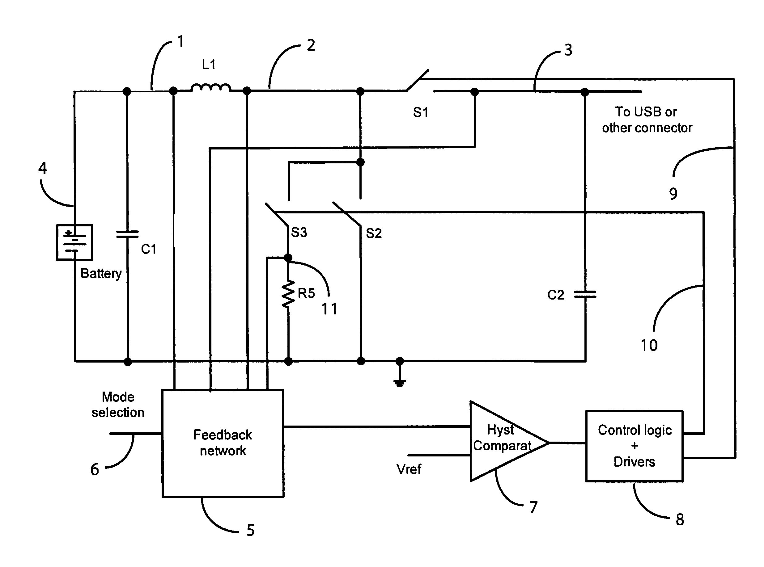
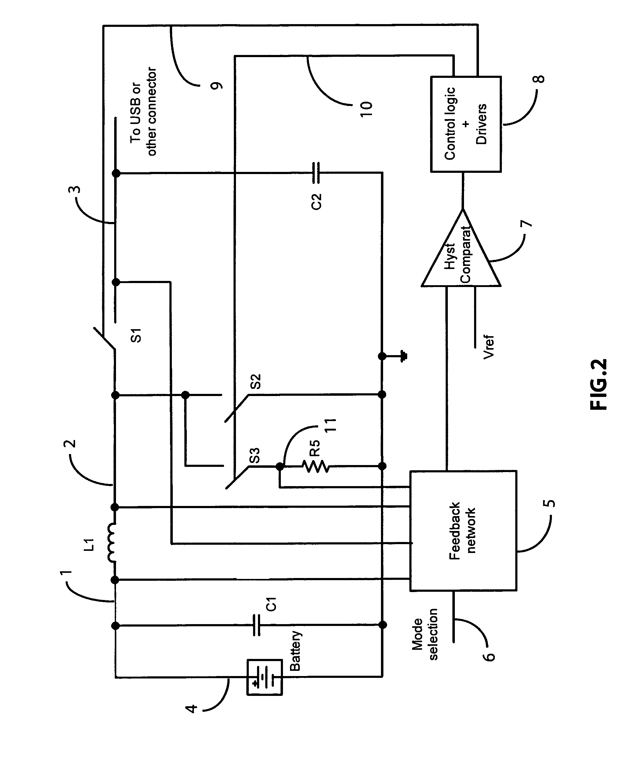
[0059]The present invention, in the embodiment shown in FIG. 2, describes a bidirectional power converter that, when the current in the inductor L1 flows from left to right, that is from the node 1 to the node 2, operates as a boost regulating the voltage at the node 3 to be higher than the voltage of the battery 4 on the left side of the schematic. When the current in the inductor L1 flows from right to left, that is from the node 2 to the node 1, the converter operates as a buck regulating the current or the voltage of the battery starting from a higher voltage at the node 3.

[0060]The switch S1 represents the high side power transistor, and generally is switched in opposition of phase with respect to the switch S2 that represents the low side power transistor. The switch S3 operates substantially in phase with the switch S2 and its main purpose is to sense the voltage of the switching node 2 when the low side is turned on and to report it to the positive terminal of the re...


PUM


Abstract

A novel switching hysteretic bidirectional power converter is presented. The converter includes the generation of a synthetic ripple signal and feedback networks to hysteretically control the power converter both when the converter operates as a boost converter with the flow of power in one direction, and when the converter operates as a buck power converter with the flow of power in the opposite direction.The presented approach provides a switching converter with a much simpler control method with respect to conventional inductive bidirectional power converters. The hysteretic control provides stable operation in all conditions with excellent load and line transient response. Furthermore this allows the operation of the bidirectional power converter with much higher switching frequencies with respect to state of the art conventional approaches, thus reducing the cost and size of the passive components storing energy during the conversion.Since bidirectional switching power converters are used mainly when the flow of power is bidirectional, the typical application involves the charging and discharging of batteries, and as part of this novel approach, an hysteretic battery charger including hysteretic constant current and constant voltage control is introduced as part of a larger bidirectional switching power converter.

Description

BACKGROUND OF THE INVENTION[0001]1. Field of the Invention[0002]The present invention is in the field of power converters. The present invention is further in the field of semiconductor switching power converters. The present invention further relates to the field of integrated hysteretic control methods for switching power converters and circuits. The present invention is further in the field of integrated switching power converters. The implementation is not limited to a specific technology, and applies to either the invention as an individual component or to inclusion of the present invention within larger systems which may be combined into larger integrated circuits.[0003]2. Brief Description of Related Art[0004]Modern electronic applications require power management devices that supply power to integrated circuits or more generally to complex loads. In general, power switching converters are becoming more and more important for their compact size, cost and efficiency. The switc...

Claims


Application Information

Patent Timeline
Patent Type & Authority Patents(United States)
IPC IPC(8): H02J7/00
CPCH02J7/0052H02J7/0065H02M3/1582H02J2007/0059H02J2007/0062H02J7/00H02J2207/20
Inventor MENEGOLI, PAOLOMARINO, FABIO ALESSIO
Owner QUALCOMM INC
Why Eureka
Try Eureka