System and method for ethernet protection switching in a provider backbone bridging traffic engineering domain

a technology of backbone protection and traffic engineering, applied in the field of communication networks, can solve the problems of not being able to easily scale in large networks, the mechanism is limited to link failure, and the metro and backbone networks have quite different requirements, so as to achieve the effect of simple and efficien

Active Publication Date: 2013-05-14
TELEFON AB LM ERICSSON (PUBL)
View PDF6 Cites 2 Cited by
  • Summary
  • Abstract
  • Description
  • Claims
  • Application Information

AI Technical Summary

Benefits of technology

[0023]The present invention provides a 1:1 bidirectional linear protection switching capability in a PBB-TE domain leveraging on the existing IEEE 802.1Qag Connectivity Fault Management (CFM). CCMs, and RDI field. The present invention also provides a simplified and efficient solution, which is well aligned to employ Ethernet technology.

Problems solved by technology

However, metro and backbone networks have quite different requirements than enterprise LANs.
However, these mechanisms are limited to link failures and are not designed to easily scale in large networks.
Furthermore, they do not support sub-50 ms protection switching in either a ring or linear environment.
In addition, since spanning tree protocols are not used in PBB-TE, this also excludes their use from the onset as a potential solution for offering PBB-TE trunk resiliency.
Direct application of the G.8031 mechanisms on in a PBB-TE domain introduces additional complexity as the advent of the APS Protocol Data Unit (PDU) for signaling purposes contains substantial redundant information leading to a non-cost efficient solution.

Method used


Image

  • System and method for ethernet protection switching in a provider backbone bridging traffic engineering domain
  • System and method for ethernet protection switching in a provider backbone bridging traffic engineering domain
  • System and method for ethernet protection switching in a provider backbone bridging traffic engineering domain

Examples


Embodiment Construction

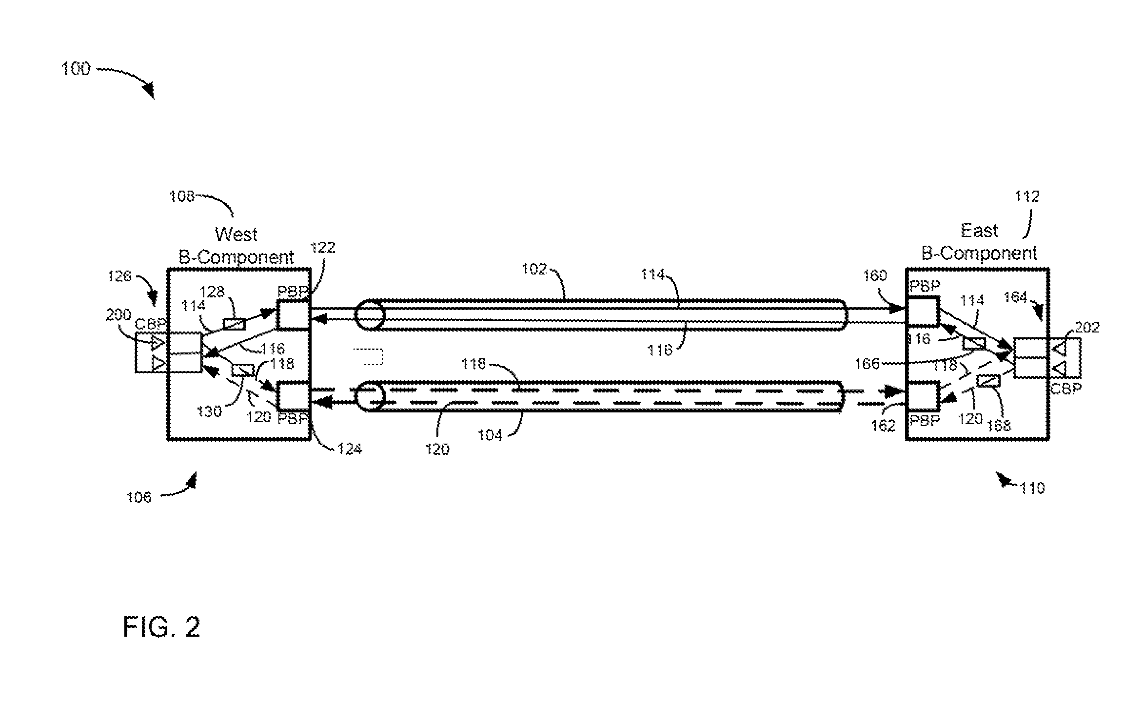
[0033]The present invention is a system and method for Ethernet protection switching in a PBB-TE domain. The present invention provides a 1:1 bidirectional linear protection switching capabilities in a PBB-TE domain. In a ABB-TE domain, Backbone Edge Bridges (BEBs) mark the demarcation between the Provider Backbone Bridged Network (PBBN) of interest and the networks attached to it. These BEBs are assumed to be B-BEBs or IB-BEBs each containing a B-Component. The protection domain is defined to be the area between the Customer Backbone Ports (CBPs) on the different B-Components of the involved BEBs. ESPs are provisioned from one BEB to the other, each one identified by the tuple . Each ESP represents a unidirectional path and the ESP pairs that form the bidirectional path define a PBB-TE trunk. The ESPs belonging to the same PBB-TE trunk are co-routed, but may also be identified by different B-VIDs.

[0034]FIG. 2 is a simplified block diagram of a network 100 illustrating PBB-TE trunk ...


PUM


Abstract

A method of providing protection switching on a backbone network includes configuring a service instance table for a first port of a first bridge. The service instance table includes a Virtual Local Access Network (VLAN) identifier entry for one or more service instances. The method also includes mapping data traffic received at the first bridge onto a first trunk by setting a VLAN identifier entry for a first service instance and transmitting data traffic to a second bridge on the first trunk in accordance with the mapping and monitoring the first trunk for faults by exchanging continuity check messages with the second bridge over the first trunk. The method additionally includes, upon detecting a fault, remapping data traffic for the first service instance by changing the VLAN identifier entry for the first service instance and transmitting data traffic to the second bridge in accordance with the remapping.

Description

CLAIMING BENEFIT OF PRIOR FILED U.S. APPLICATION[0001]This application is a continuation of International Application PCT / IB2008 / 002936, with an international filing date of Oct. 31, 2008, which corresponds to the national-stage entry U.S. patent application Ser. No. 12 / 441,440, filed Dec. 8, 2009 now U.S. Pat. No. 8,144,576 and which claims the benefit of U.S. Provisional Application No. 60 / 984892, filed Nov. 2, 2007, and the contents of all of the preceding are hereby incorporated by reference herein.TECHNICAL FIELD[0002]The present invention relates generally to communications networks, and in particular, to communications networks that employ systems and methods of Ethernet protection switching in a Provider Backbone Bridging Traffic Engineering (PBB-TE) domain.BACKGROUND OF THE INVENTION[0003]Over the past few years, Ethernet has become the undisputed leading Local Area Network (LAN) technology due to the intrinsic characteristics of the technology, such as being simple to impl...

Claims


Application Information

Patent Timeline
Patent Type & Authority Patents(United States)
IPC IPC(8): G01R31/08H04L69/40
CPCH04L43/065H04L43/0811H04L41/0654H04L41/06
Inventor SALTSIDIS, PANAGIOTISJULIEN, MARTINMONETTE, SYLVAIN
Owner TELEFON AB LM ERICSSON (PUBL)
Why Eureka
Try Eureka