Electronic scanning type radar device, estimation method of direction of reception wave, and program estimating direction of reception wave

a radar device and electronic scanning technology, applied in measurement devices, multi-channel direction-finding systems using radio waves, instruments, etc., can solve the problems of not being suitable for vehicle-mounted radars, not being designed for vehicle-mounted devices, and not being able to use vehicle-mounted radars. to achieve the effect of reducing the number of detection cycles, enhancing the recognition performance of the final distance and the recognition of the final distance and the direction of the targ

Active Publication Date: 2013-05-21
HONDA ELESYS OF YBP HI TECH CENT
View PDF30 Cites 181 Cited by
  • Summary
  • Abstract
  • Description
  • Claims
  • Application Information

AI Technical Summary

Benefits of technology

[0106]According to the embodiment described in (1) above, the target consolidation processing unit relates the same target in the present and in the past to one another. Then, the target consolidation processing unit performs an averaging process of the correlation matrix. Therefore, regardless of the fluctuation of the distance to the target, the eigen value computation in the subsequent direction detection process and the spectrum computation (such as MUSIC) can be performed accurately. Thus, compared to the instance in which the computation is performed using the correlation matrix of only the present time, it is possible to enhance the recognition performance of the final distance and direction of the target.
[0107]In addition, according to the embodiment described in (1) above, a plurality of correlation matrices or complex number data are stored for each target. Since all of these are used to perform the averaging process, the recognition performance of the final distance and direction of the target can be further enhanced regardless of the fluctuation in the distance to the target.
[0108]In addition, according to the embodiment described in (13) above, the number of detection cycles of the correlation matrix used to average the correlation matrix are altered optionally for each target based on the relative velocity with respect to the target. Thus, when the distance to the target is fluctuating, the number of detection cycles is reduced. Meanwhile, when the distance to the target is stable, the number of detection cycles is increased. As a result, the correlation matrix filtering unit can have an appropriate filtering characteristic based on the condition of the relative velocity with respect to each target. Consequently, the recognition performance of the final distance and direction of the target can be further enhanced regardless of the fluctuation in the distance to the target.
[0109]In addition, according to the embodiment described in (11) above, the averaging weight coefficient used to average the correlation matrix can be varied for each target based on the relative velocity with respect to the target. As a result, the correlation matrix filtering unit can have an appropriate filtering characteristic based on the condition of the relative velocity with respect to each target. Consequently, the recognition performance of the final distance and direction of the target can be further enhanced.
[0110]In addition, according to the embodiment described in (11) above, when the amount of change of the lateral position, obtained by the direction and the distance in the past and in the present, exceeds a predetermined range, the weight coefficient used to compute a weighted average is altered according to each target. In other words, the correlation matrix filtering unit can have an appropriate filtering characteristic such that the number of past cycles to be averaged is reduced, or, the weighting coefficients are made variable and the number of linkage is thus substantively reduced. Consequently, the recognition performance of the final distance and direction of the target can be further enhanced.
[0111]In addition, according to the embodiment described in (3) above, the complex number data of the target frequency is stored. As a result, the past data stored in the memory equals, for each target, the number of channels of the plurality of original antennas×2 (the complex number data of the real part and the imaginary part). Therefore, compared to the case in which the storing is made simply by the correlation matrix, the memory size can be reduced.

Problems solved by technology

Therefore, even if the snapshot number is increased nebulously, the accuracy of detecting the arrival direction of the reception wave does not necessarily increase.
Therefore, it is not suitable to use these methods for a vehicle-mounted radar whose relative distance to the target and relative velocity fluctuate rapidly.
This method is not designed to be used for a vehicle-mounted device.
Therefore, it is not suitable to use these methods for a vehicle-mounted radar whose relative distance to the target and relative velocity fluctuate rapidly.

Method used


Image

  • Electronic scanning type radar device, estimation method of direction of reception wave, and program estimating direction of reception wave
  • Electronic scanning type radar device, estimation method of direction of reception wave, and program estimating direction of reception wave
  • Electronic scanning type radar device, estimation method of direction of reception wave, and program estimating direction of reception wave

Examples


first embodiment

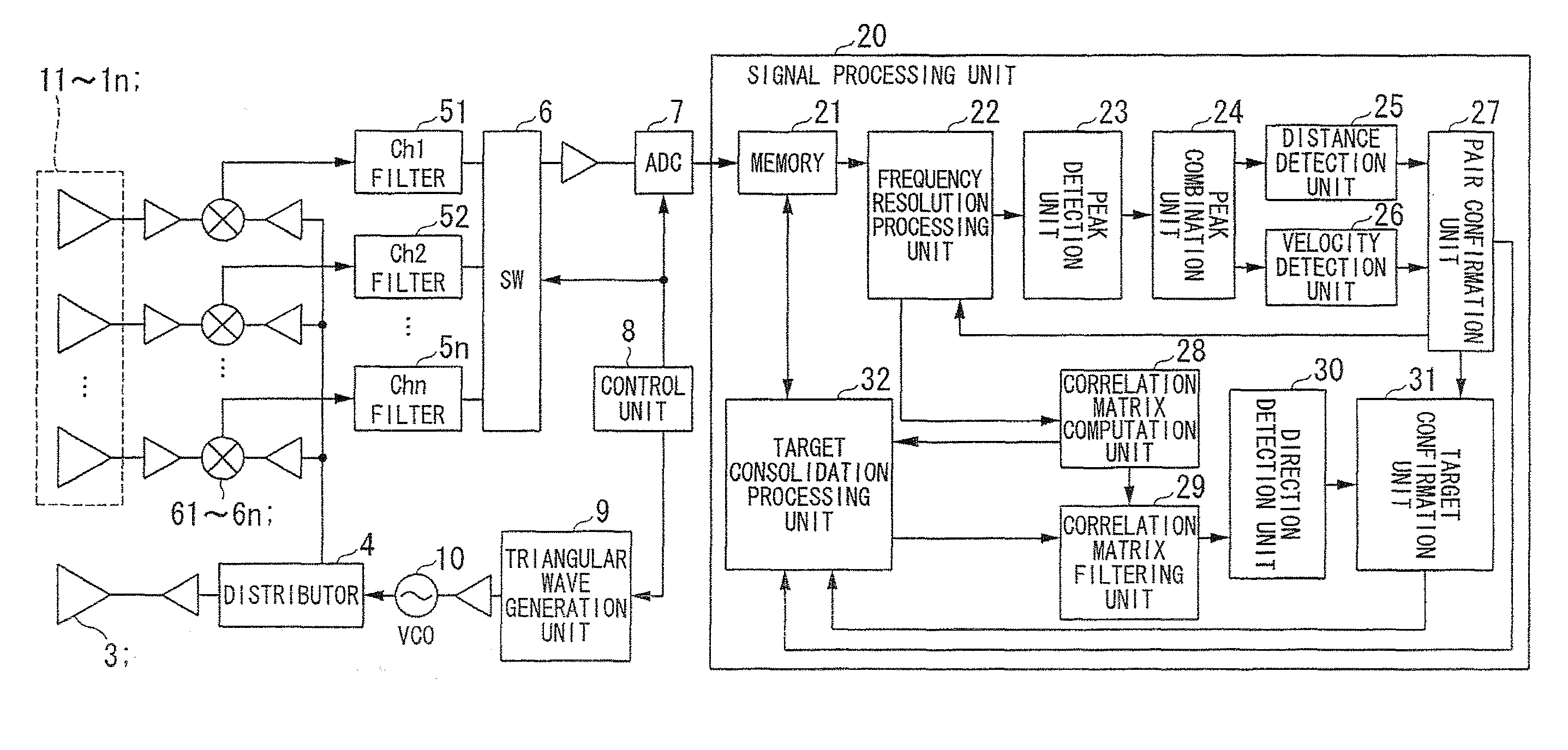
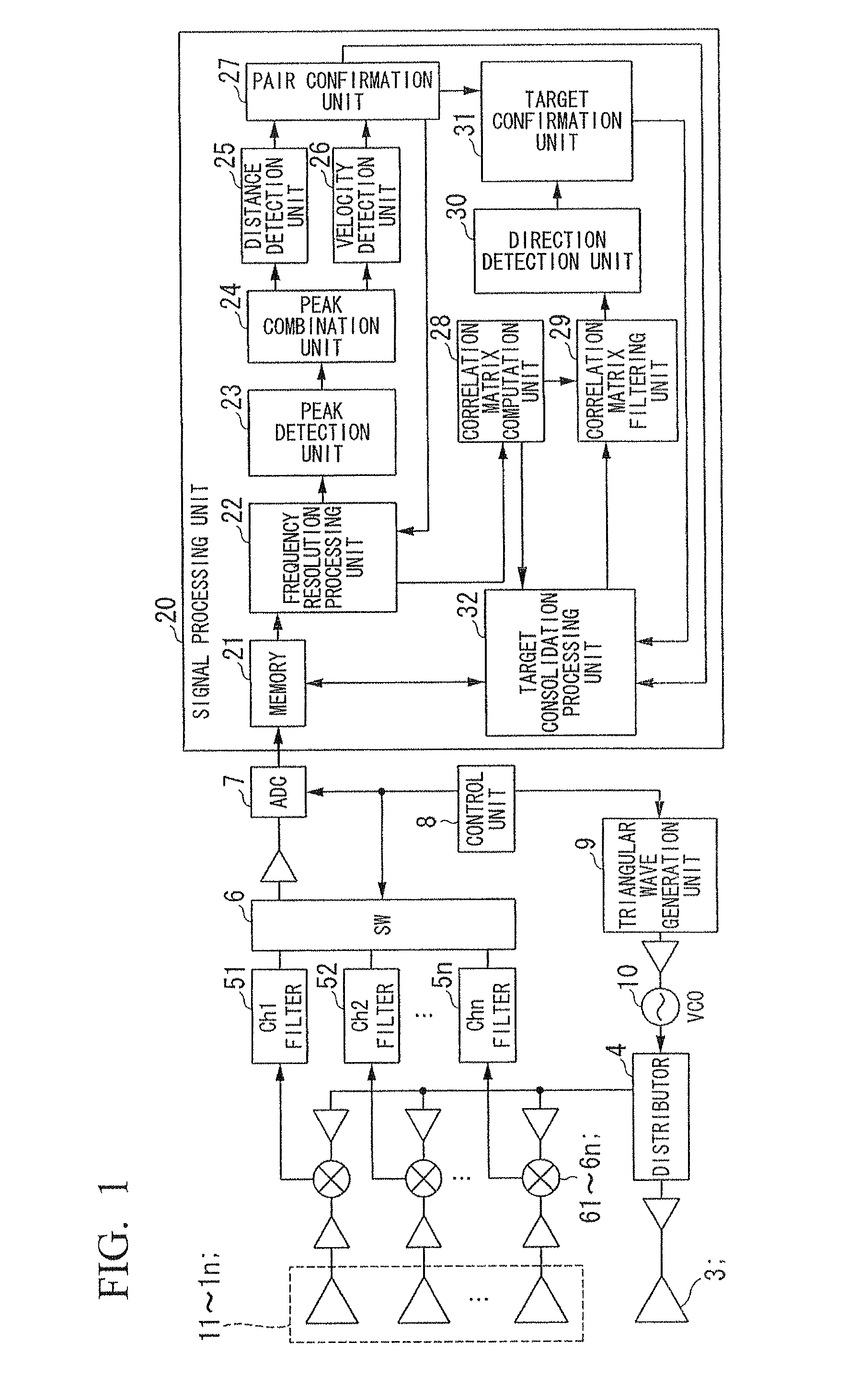
[0213]Hereinafter, a first embodiment of an electronic scanning type radar device (FMCW type milliwave radar) according to the present invention is described with reference to the diagrams. FIG. 1 is a block diagram showing an example of a configuration of the first embodiment.

[0214]In this diagram, the electronic scanning type radar device according to the first embodiment includes a reception antenna 11˜1n, a mixer (beat signal generation unit) 61˜6n, a transmission antenna 3, a distributor 4, a filter 51˜5n, a SW (switch) 6, an ADC (A / D converter) 7, a control unit 8, a triangular wave generation unit 9, a VCO 10, and a signal processing unit 20.

[0215]The signal processing unit 20 includes a memory (memory unit) 21, a frequency resolution processing unit 22, a peak detection unit 23, a peak combination unit 24, a distance detection unit 25, a velocity detection unit 26, a pair confirmation unit 27, a correlation matrix computation unit 28, a correlation matrix filtering unit 29, ...

second embodiment

[0319]Hereinafter, an electronic scanning type radar device according to a second embodiment of the present invention is described with reference to FIG. 18. FIG. 18 is a block diagram showing an example of a configuration of the electronic scanning type radar device according to the second embodiment.

[0320]Similar to the first embodiment, the second embodiment is configured so that the direction is estimated only with a super-resolution algorithm. The same reference numeral is used for the configuration which is similar to the first embodiment shown in FIG. 1. Hereinafter, the aspects which are different from the first embodiment are described.

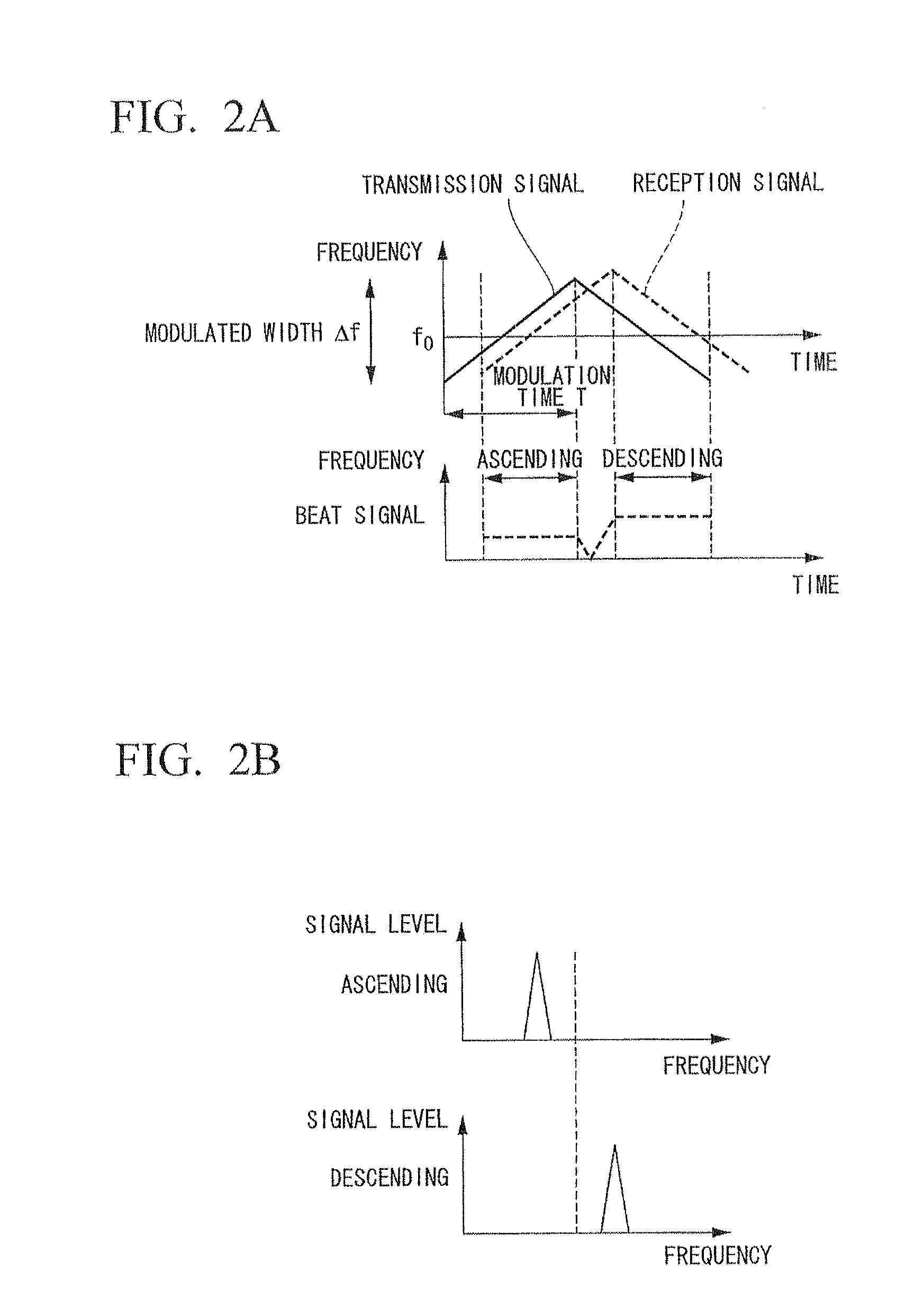
[0321]The frequency dissolution processing unit 22B converts the beat signal of the ascending region and the descending region for each antenna into complex number data, and outputs the frequency point indicating its beat frequency and the complex number data to the peak detection unit 23B.

[0322]Then, the peak detection unit 23B detects the p...

third embodiment

[0338]Hereinafter, an electronic scanning type radar device according to a third embodiment of the present invention is described with reference to FIG. 21. FIG. 21 is a block diagram showing an example of a configuration of the electronic scanning type radar device according to the third embodiment.

[0339]According to this third embodiment, different from the first embodiment, an estimation of a direction is first made using a DBF (Digital Beam Forming) which has a lower resolution performance compared to a super-resolution algorithm such as the MUSIC Method. Next, a super-resolution algorithm is used to estimate the direction from a correlation matrix which has undergone an averaging process. The same reference numeral is used for the configuration which is similar to the first embodiment shown in FIG. 1. Hereinafter, the aspects which are different from the first embodiment are described.

[0340]As shown in FIG. 21, a DBF processing unit 40 is provided between the frequency dissolut...


PUM


Abstract

An electronic scanning type radar device mounted on a moving body includes: a transmission unit transmitting a transmission wave; a reception unit comprising a plurality of antennas receiving a reflection wave of the transmission wave from a target; a beat signal generation unit generating a beat signal from the transmission wave and the reflection wave; a frequency resolution processing unit frequency computing a complex number data; a target detection unit detecting an existence of the target; a correlation matrix computation unit computing a correlation matrix from each of a complex number data of a detected beat frequency; a target consolidation processing unit linking the target in a present detection cycle and a past detection cycle; a correlation matrix filtering unit generating an averaged correlation matrix by weighted averaging a correlation matrix of a target in the present detection cycle and a correlation matrix of a related target in the past detection cycle; and a direction detection unit computing an arrival direction of the reflection wave based on the averaged correlation matrix.

Description

CROSS-REFERENCED TO RELATED APPLICATION[0001]This application is a National Stage entry of International Application PCT / JP2008 / 073606, filed Dec. 25, 2008, which claims priority to Japanese Patent Application No. 2007-331567, filed Dec. 25, 2007, Japanese Patent Application No. 2008-002312, filed Jan. 9, 2008, and Japanese Patent Application No. 2008-002313, filed Jan. 9, 2008, the disclosure of the prior applications being incorporated in their entirety by reference.TECHNICAL FIELD[0002]The present invention relates to an electronic scanning type radar device, suitable for mounting on a vehicle, which uses a reflection wave from a target corresponding to an emitted transmission wave in order to detect the target. The present invention also relates to an estimation method of a direction of a reception wave, and a program estimating a direction of an incoming wave to be used for the above estimation method.[0003]The present application is based on Japanese Patent Application No. 200...

Claims


Application Information

Patent Timeline
Patent Type & Authority Patents(United States)
IPC IPC(8): G01S13/00G01S13/931
CPCG01S3/74G01S13/345G01S13/584G01S13/426G01S13/04G01S13/931G01S2013/9375G01S2013/93271
Inventor KANAMOTO, JUNJIAKIMOTO, HIROYUKI
Owner HONDA ELESYS OF YBP HI TECH CENT
Why Eureka
Try Eureka